Sharing High-Tech Tools Creates Rocky Mountain High
| + click image to view full diagram |
) |
| |
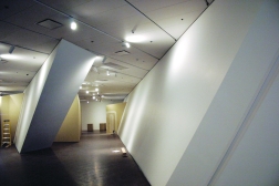
Coordinate geometry made alignment difficult. X-Y-Z survey coordinates were incorporated into the 3D model. All primary columns, sloping and vertical, were detailed and fabricated with shop-drilled control holes designed to hold a surveyors prism at a theoretical spot in space. A second survey location was fabricated into the member using a center-punch mark to locate and install a reflective target on the surface of the column. High-tech transits were programmed with the coordinates.
Zimmerman fabricated oversized bolt holes to allow the erector to use full-size fit-up pins. This was key to the fit-up, allowing easy field adjustment for imperfections in plate alignment, says LPR.
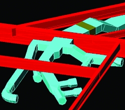
During design, Arup checked the structure and the mechanical service for clashes. The challenge was to place ductwork in the walls to minimize shaft space. The museum also wanted to minimize water piping in the art galleries. That meant home-running ductwork to central mechanical rooms containing air handlers. That was difficult because risers sloped every which way.
| + move your mouse over the image to view the model diagram of this view |
 |
| |
Arup laid out every duct run in 3D. When a run hit a steel member, a beam penetration was indicated on shop drawings and cut out during fabrication. Arup has already used 3D mechanical layouts on three other projects. Mostly it is used for mechanical rooms and tight ceiling-void pinch-points, says McConahey.
For the Loveland, Colo., office of U.S. Engineering Co., the mechanical subcontractor with a $6.3-million contract, the interface with other subs during Mortensons preconstruction phase was novel and helpful, as was the 3D solid model.
The jobs many bends were much easier to visualize in 3D. We used more offsets than we ever could have imagined and more support steel to support plumbing, says Daniel Kern, U.S. Engineerings project manager.
On the air side, it was also difficult to follow the planes.Nothing was square so we couldnt lay out normally, he says.
U.S. Engineering got involved in June 2003, replacing the original mechanical sub that had financial woes. We had to jump in quickly on the 3D portion, says Kern.
It was a learning process. Despite all the efforts, Kern says there were several collisions on each floor.
 |  |
| |
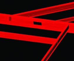
The electrical conduit followed. To lay out systems, Dynalectric Co. of Colorado, which has a $5.4-million contract, coordinated with mechanical and sprinkler contractors through Mortenson. The coordination was incredibly critical to locate their equipment, our equipment and how the systems run, says Craig W. Clark, president of the Lakewood, Colo.-based firm. I wouldnt say it was perfect but it worked quite well, he adds.
Clark says that with so many wall inclines, getting access to the top of each for lighting fixtures was difficult. Workers had to use mechanical lifts with arms, instead of ladders. The installation was about 40% more labor-intensive compared to a typical building. Its an OK job. I wouldnt say we got rich, he says.
Mortenson is already basking in the glow of its accomplishment, especially compared with Disney, although the concert hall was twice as big and in a high seismic zone. But Disney had 10,000 requests for information; DAM has 1,300. Disney, which opened in late 2003, has an outstanding claim, rumored close to settlement, of about $40 million. DAM has no claims pending or expected.
That said, without Disney there may not have been a DAM for Mortenson.
| ENR Building Report Questionnaire: bim515.doc, |

