Sharing High-Tech Tools Creates Rocky Mountain High
| Sequence 13 |
 |
 |
 |
 |
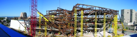
| Sequence 13 had more than 50 sliedes to help workers visualize steps, both in 2D (top) and 3D (bottom three) (Images courtesy of LPR) |
Blurred lines between design and construction phases and high-tech aids aside, 2D construction documents still rule. The design consultants 3D design models were given to the contractor for use without warranty, as a geometric control. This was done in parallel with 2D documents. It was a big risk for the designers, says Shannon Rogers, Mortensons model manager.
Though techno-soothsayers predict the coming of a single master digital model, for this job there was still one on the design side and one on the construction side. The architect and the CM each needed a full-time model keeper. One of the tasks was to coordinate with each other to keep the models in sync.
Mortensons 3D digital model, built from design-team models, included steel, concrete, ductwork, piping, conduit, fire sprinklers, scaffolds, temporary steel, falsework, crane locations, even rigging frames for steel lifts. It was used during construction for development and coordination of shop drawings, generated in 2D for field use. Mortensons 4D model, which added the element of time, was used for visualization and construction sequencingfor virtual prebuilding as a way to educate subs and anticipate and eliminate field problems.
Success hinged on getting the structural engineers digital wire-frame model to the steel detailer to create a solid model. At first, that did not sit well with the architect. I dont think any of us [on the design team] going in knew we were going down that roadgiving the contractor our 3D models, says Maria Cole, Daviss associate on DAM.
Believer
Skeptical at first, Davis is now a believer in sharing. Having the contractor on board early, studying the architects 3D model and physical scale models, and offering suggestions on constructibility, allows you to imagine spaces beyond what were capable of in 2D, Cole says.
Sharing digital models still puts challenges on design, says the architect. Certain things, lost in translation, need to be redrawn. Working with the model is cumbersome and time-consuming because it is information-intensive.

For the rest of the consultants, the process differed from the norm in that full 3D models were provided by the architect and the contractual deliverable included 3D versions of the design, says Erin McConahey, an associate principal in Arups Los Angeles office.
Arup, also the mechanical structural consultant, extracted valuable information from the architects volumetric digital models, including edge and top of flange and centerline of steel. Thanks to 3D, the firm was able to coordinate the frame, ductwork and piping, minimizing coordination-related requests for information. Every beam penetration was factory-cut and its location known during the design phase, says McConahey.
On the business side, Mortenson learned on Disneythe hard waythat to make the process work it is imperative to develop specific, detailed subcontractor contract language on generation and hand-off of electronic data. But all the models in the world wont help if people in the field arent familiar with the system. Its a learning process, says Walsh.
Biggest Bear

The steel frame was the biggest bear on the project. Mortenson had a process where issues were identified in a pre-detailing request and resolved through Web meetings and other correspondence. That, combined with use of the 3D digital model, prevented 1,200 collisions of steel elements and sped steel erection to the finish line three months early. Mortenson then gave nearly $400,000 back to the owner. The frame consists of mostly sloping columns with diagonal braces to resist lateral loads. There are about 40 different slopes. Perimeter walls lean outward from the horizontal 40 to 84. The only vertical elements other than some interior columns are elevator shafts.
The inclined walls generate permanent lateral loads throughout the floor system, which equate to similar design loads in a seismic zone, says Atila Zekioglu, an Arup principal. Horizontal beams, strategically placed, counteract instability of the inclines by acting like a tension tie.
Floor plates and individual roof planes are used as diaphragms to distribute lateral loads, with extensive use of drag-strut connections to distribute concentrated horizontal forces into the composite concrete-on-metal-deck diaphragm and back into perimeter walls and interior braced planes. Additional deck bracing and steel plates are under the deck in locations of high plane shear forces. Inclined walls are supported at ground level on vertical planes, where shear forces are transferred to reinforced concrete walls. Interior walls are supported on steel bracing in the vertical plane which in turn takes shear forces to caisson foundations.
Precambering was required on some joints in the frames vertical and horizontal directions to accommodate up to 3 in. of deflection when shoring was removed.
Because of the unstable geometry, the erection sequence took precedence during preconstruction meetings. Sources say that when LPR spoke, everyoneeven the structural engineerlistened.
 |
| |
LPR created an 18-sequence erection plan for the 2,740 tons of steel. The plan, which included shoring, rigging design and crane reach drawings, was detailed in 3D, including step-by-step sequencing. Use of the 3D model in the office and the field was paramount to the projects success, says Curtis Mayes, LPRs director of preconstruction and engineering.
One of the toughest sequences was the erratic 13th, under the roofline. LPR could not figure out a reasonable way to shore the sequence, so it had to figure out how to stabilize members temporarily until other pieces were in place. Mayes used more than 50 3D slides to teach the sequence to the team.
| ENR Building Report Questionnaire: bim515.doc, |

