Shear-Stud Code Defenders Slam Recent Contentions that the Model Code is Flawed
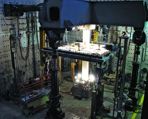
Figure R11.11.5 in the code commentary shows shear-stud layouts for three conditions, Hammill continues. In each case, the shear-stud reinforcement is clearly located at the column corners.
"The figures are to be considered part of the code requirements, as their intent is to clarify, when it is easier to show details rather than to describe them," says Hammill. "This is the layout that has always been used both in practice and in the developmental tests and is the proper interpretation of the code requirements."
Shield disagrees: "Nothing in the code says the stud rails have to come out of the corners of the column or be perpendicular to the column face at the corners."
She adds: "There is no doubt in our minds that the headed reinforcement does contribute to the shear capacity of the connection. But work completed at the University of Michigan and University of Minnesota has led us to question whether the code provisions for headed shear reinforcement in slab-column connections put stringent enough requirements on the spacing and layout of the reinforcement."
Ghali replies: "Nothing in Parra-Montesinos' [presentations at recent American Concrete Institute meetings] justifies his claim of premature failure or the need to change the code provisions for the stud-shear reinforcement."
To try to sort things out, the technical activities committee (TAC) of the Farmington Hills, Mich.-based ACI recently convened a six-person task group of engineer-practitioners and academics to study all the literature on stud rails. "TAC assembled a task group so we could provide advice to ACI leadership about how to use the ACI process to respond to the technical issues at hand," says David Lange, TAC chairman and a professor of civil engineering at the University of Illinois at Urbana-Champaign.
The group is reporting back to ACI before the next and final test in the series at MAST. The test is scheduled for late December or early January.
The goal of the final research is to develop a standard design, detailed to current practice that will show good ductility and deformation capacity during earthquakes and be economical to construct. The intention is to verify that the slab-to-column connection can undergo simulated earthquake motion, under realistic gravity loads, without failing.
The specimen has an orthogonal stud-rail layout with added diagonals radiating at 45-degree angles from column corners.
Diagonal studs are more widely spaced than the orthogonal lines to ease rebar placement, says MKA's Fields. As a representative of the Pankow Foundation, Fields has reviewed the detail for the test specimen.
"For the next round, we've drilled down into the detail to make sure that the specimen is equivalent to seismic design practice, which should remove any question about the results," says Fields.


