Harsh Conditions Put Team to the Test on Champlain Bridge
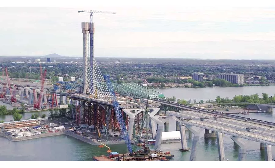
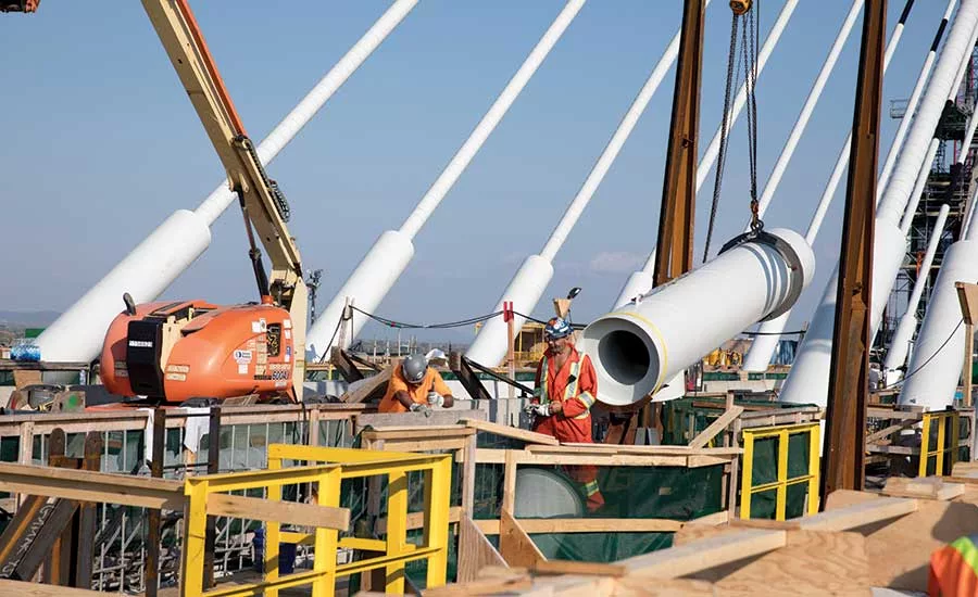
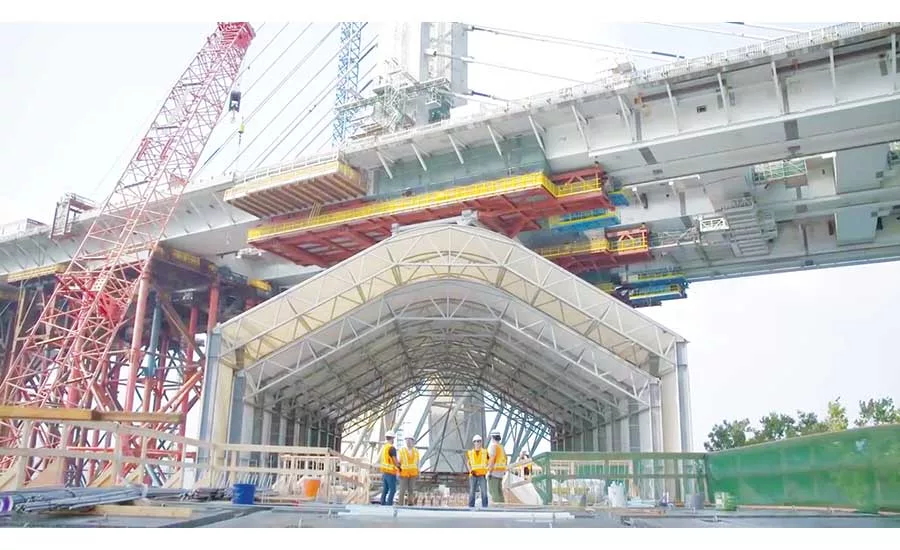
Champlain Bridge over the St. Lawrence Seaway includes 60 stay cables, with 127 strands per cable. The pylon is 170 m high, with prefabricated segments.
PHOTO COURTESY OF SIGNATURE ON THE SAINT LAWRENCE

Champlain Bridge over the St. Lawrence Seaway includes 60 stay cables, with 127 strands per cable. The pylon is 170 m high, with prefabricated segments.
COURTESY OF T.Y. LIN INTERNATIONAL
Champlain Bridge over the St. Lawrence Seaway includes 60 stay cables, with 127 strands per cable. The pylon is 170 m high, with prefabricated segments.
PHOTO COURTESY OF SIGNATURE ON THE SAINT LAWRENCE

Champlain Bridge over the St. Lawrence Seaway includes 60 stay cables, with 127 strands per cable. The pylon is 170 m high, with prefabricated segments.
PHOTO COURTESY OF SIGNATURE ON THE SAINT LAWRENCE

Champlain Bridge over the St. Lawrence Seaway includes 60 stay cables, with 127 strands per cable. The pylon is 170 m high, with prefabricated segments.
COURTESY OF T.Y. LIN INTERNATIONAL

Champlain Bridge over the St. Lawrence Seaway includes 60 stay cables, with 127 strands per cable. The pylon is 170 m high, with prefabricated segments.
COURTESY OF T.Y. LIN INTERNATIONAL
Champlain Bridge over the St. Lawrence Seaway includes 60 stay cables, with 127 strands per cable. The pylon is 170 m high, with prefabricated segments.
COURTESY OF T.Y. LIN INTERNATIONAL
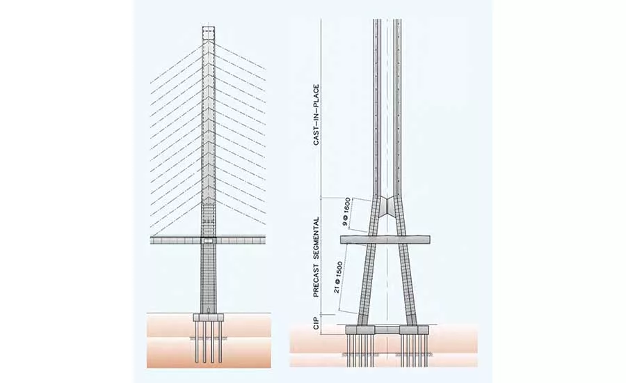
The main pylon has both cast-inplace and precast segments, plus a “bowtie” connector.
COURTESY OF T.Y. LIN INTERNATIONAL

The approach structures rest on slanting Y-shaped piers topped by steel box girders and concrete slabs.
COURTESY OF T.Y. LIN INTERNATIONAL
Designed to last 125 years despite its location in a harsh natural environment where it is part of a key international trade corridor, the Champlain Bridge will also add to Montreal’s skyline with its unusual asymmetrical cable-stayed span. The $3.1-billion project required vertical access engineering and designs for a variety of conditions, including seismicity, wind loads, ice loads, scour and the need to accommodate a future transitway.
The project—which includes another 5 kilometers of highway expansions and improvements along with the 3.4-km-long bridge over the St. Lawrence River—has been beset by challenges such as extreme winters, governmental changes and a crane operators’ strike. Signature on the Saint Lawrence (SSL), a consortium comprising SNC-Lavalin, ACS and Hochtief, faces penalties from owner Infrastructure Canada for missing its scheduled Dec. 21 completion, but it hopes to complete the bridge by next summer, and the team is in discussions with Infrastructure Canada about the penalties (ENR 11/5-12 p. 14). The contract calls for the consortium to build, operate and maintain the bridge for 30 years, but a new government in 2015 canceled the bridge tolls, so discussions about revenue are ongoing as well.
“We had a 42-month schedule, but only 30 months of good weather,” says Daniel Genest, project director with SSL. He adds that the 16-day crane operator strike in June also had a ripple effect on construction progress.
When completed, the bridge will connect the South Shore suburbs to Montreal with two three-lane corridors for traffic, a two-lane transit corridor and a separate pedestrian/bike path. It will handle 60 million vehicles a year and support approximately $15 billion in U.S.-Canada trade. It replaces a 6-km-long steel truss bridge with concrete approach viaducts that opened in 1962 and has deteriorated due to deicing salts and inefficient drainage. “It cost up to $100 million a year just to maintain the old bridge,” says Guy Mailhot, chief engineer with Infrastructure Canada.
 The location of the bridge itself is a challenge. The site is separated from the St. Lawrence Seaway on the east side by a dike, and bridge piers had to avoid both. “The channel [location] had a lot to do with our means and methods,” says Marwan Nader, senior vice president with T.Y. Lin International, part of the design and construction group led by Dragados Canada, Flatiron Constructors Canada and EBC. T.Y. Lin International is partnered with SNC-Lavalin and International Bridge Technologies on the design of the bridge. Bridge piers have to withstand the river current that can reach up to 20 km per hour. With a port just 5 km downstream, the team had to request four- to eight-hour windows of time to lift segments into place, says Genest. The river is up to 2.3 km wide, but only 4-5 meters deep.
The west approach has 19 piers in the water with 38 precast spread footings installed using a floating foundation installer, built in Belgium and named “Poseidon” by local schoolchildren, and six piers on land on cast-in-place spread footings. The east approach has four piers on cast-in-place spread footings and four on pile foundations.
The 529-m-long cable-stayed section includes a single 170-m-tall reinforced concrete pylon resting on two footings, each 1,000 cu m. The pylon was built with 44 prefabricated lower segments, a cross-beam composite to the pylon and 22 cast-in-place upper segments. There are 15 main span segments, each weighing 850 tonnes. The 60-m by 12.5-m segments consist of three assembled boxes.
Looking for quick answers on construction and engineering topics?
Try Ask ENR, our new smart AI search tool.
Ask ENR →
The 2,044-m-long west approach structure and 762-m-long east approach structure comprise 600 composite steel box girders up to 80 m long, topped by 9,600 concrete deck slabs. “We had 10 major shops fabricating steel and concrete globally,” says Genest. “It was quite a quality assurance/quality control challenge.” Some 1,600 workers at peak last month had just three jetties to assemble and place bridge elements.
The main span tower’s lower legs incline toward one another until they reach the cross-beam, then the upper towers are straight. Strand jacks lifted the precast 350-tonne “bowtie” into place right above the existing crossbeam and post-tensioned and grouted it. “We designed it four times,” says Nader. “It went from steel to composite to cast-in-place to precast. It takes a lot of the load, acting as a [second] crossbeam.”
“We had a 42-month schedule, but only 30 months of good weather.”
– Daniel Genest, Project Director, SSL
The W-shaped pier caps were originally to be concrete, but changing them to steel eliminated the amount of material needed by more than half, to 200 tonnes from 550 tonnes, says Nader. The caps were erected in two pieces on each corresponding pier leg, connected on site at a center splice. The original design called for steel connection with some 90 anchor rods. This connection proved challenging as it required mill-to-bear surfaces on the steel mating faces. The team came up with an alternative composite concrete post-tensioned connection for 31 of the 37 pier caps.
The W-shaped inclined piers are a result of an architectural mandate from the owner. In addition to visual standards, the bridge design had to meet a variety of criteria. “Ice loading is a big deal,” says Nader. “In winter, there are sheets of ice six to nine inches thick.” For the ice abrasion zone, the team used a special ultra-high-strength concrete mix. Another specific concrete mix was used for the deck slab to protect against deicing salts.
In late 2017, to accelerate the schedule, the team made a strategic decision to relocate the deck closure joint of the main span to allow concurrent erection from the east and west banks. The bridge’s single tower supports 15 pairs of stay cables designed in a harp arrangement. Typically, crews would complete the tower first, then erect the deck segments one by one from the tower onward, each supported by a corresponding stay. After moving the closure joint location further west, the team was able to erect the main span from both sides, says Nader. This resulted in a 50-m cantilever from the first east pier that could not be supported using temporary shoring due to the “no construction zone” requirement to keep the channel open.
“We decided to support the cantilever with a king post tower, with temporary stays anchored at the second east pier and at segments MS12 and MS13,” says Nader. “Effectively, the east cantilever was supported by a temporary cable-stayed bridge.” The scheme saved two months, he says, and the closure joint will be completed after the holiday season.
This took place with the concurrent advancement of the heavy lift segments for the main span tower. Each fully assembled 12.5-m by 57.3-m segment weighs 850 tonnes and was erected using a custom-built dynamic lifting frame and a moveable lifting beam.
When Quebec-based AGF Access Group got the contract to provide access on the bridge, the first thing it did was talk to its special projects division. The company pledged to supply 85% of the access equipment for the bridge project, including mast climbers for the towers, traditional swing-stage scaffolding and ring-tied stairs, as well as temporary and permanent elevators inside and outside the bridge’s pylon. In addition to standard access gear, AGF also saw a particular engineering challenge in accessing the undersides of the cantilevered spans.
Building a Better Platform
“They were building the bridge on a cantilevered segmented approach—bridge sections assembled and mounted on a cantilever,” says Alex Di Domenico, vice president for major projects at AGF. “We came up with some custom bolting platforms for that.” AGF provided three traveling aluminum access platforms instead of the typical steel platforms used in the industry, which features fully electrical controls to travel along the cantilevered sections of the bridge.
The traveling platforms were a crucial staging area for construction, together providing full coverage of the bridge’s 55-m width. The 19-m-wide platforms, designed to retract to 16 meters when stored at the ends of the bridge, boast a 4,000-kilogram capacity when fully extended. “That was the idea—one tonne for personnel, three for materials,” says Sony Trudel, engineering director for special projects at AGF. “When you have all three platforms together, you have [a working area] almost the size of an ice hockey rink.”
Building aluminum-based work platforms of this scale isn’t a standard product for AGF, but the demands of the contractor drove their engineers to come up with a solution, says Di Domenico. “One of the key features of the cantilever method is having as little weight as possible on cantilevered ends,” he explains. Having aluminum platforms made the equipment easier to work with, he adds.
The three platforms are electronically controlled and can travel along the bottom of the main span without assistance or additional equipment. Because they were designed alongside the bridge itself, they are able to traverse elements of the bridge’s underside that would impede off-the-shelf access platforms. AGF Group plans to refurbish them as permanent maintenance equipment stored below platform level once construction is completed. “We really believe that this approach can be used on our future projects in North America,” says Di Domenico.
By Aileen Cho in Montreal, with Jeff Rubenstone


