Constructions Accidents
What Florida Bridge Collapse Report Leaves Unexplained
The transportation board describes FIGG’s alleged design flub without filling in the why

"For reasons unexplained.”
Those are the words used last week by one of the National Transportation Safety Board’s investigators, engineer Daniel S. Walsh, in seeking the “why” behind the key design error the board says caused last year’s deadly pedestrian bridge collapse in Miami.
The bridge, a 174-ft-long concrete truss, was to provide a crossing over a busy road for pedestrians at Florida International University. In its report, the NTSB stated that its investigators could not find another single-truss concrete structure built anywhere in the world.
Before it was finished, and five days after the precast structure was rolled into position over the road, it collapsed.
Designed by Tallahassee-based FIGG Bridge Engineers, the structure had a single row of diagonals and verticals connecting the truss’s bottom chord, its walking surface, and its narrower top, which served as a canopy. A pylon with cables connecting to the bottom section of the truss was to have added some stability but no significant load-bearing capacity. It would have been mainly for appearance.
Since the collapse, engineers have speculated about the wisdom of designing such a novel structure and the complications of analyzing it.
“It’s not even a normal truss,” one engineer who asked not to be identified observed. He noted that the single row of diagonals in the truss’s center were at unusual angles, adding to the structure’s singular appearance but complicating any analysis.
Looking for quick answers on construction and engineering topics?
Try Ask ENR, our new smart AI search tool.
Ask ENR →
For its part, FIGG Bridge engineers blames the collapse on the contractor it worked for under a design-build contract, claiming the company introduced loads while rolling the structure into place. FIGG also claims the contractor failed to follow design instruction for concrete roughening at the failed node that would have helped resist shear forces and a concrete blowout at the last diagonal at the bridge's north end. When the collapse occurred, the final connections at that end had not been made across a short span and cracks were spreading in the region.
SLIDE FROM NTSB PRESENTATION OF OCT., 2019
The structure fell as a crew was re-tensioning a rod running through the last diagonal at the north end, according to instructions prepared by FIGG. The hope was that that would stop the spreading cracks. Importantly, the NTSB found that the plan for re-tensioning the bridge structure—a remedial action ordered by FIGG's engineer of record, Denney Pate—was undertaken without having been reviewed and approved by an engineer, as it should have been.
Additionally, investigators stated that FIGG, construction engineering and inspection firm Bolton Perez & Associates; Florida DOT engineers and Florida International University all had the authority to close the road.
Based on an elaborate analysis, FIGG claims roughened concrete would have averted the tragedy and developed the needed resistance to the outward push of diagonal number 11.
The NTSB largely rejected that theory. While noting that contractors failed to roughen certain portions of the bridge, the NTSB concluded that roughening likely would not have prevented the structure from collapsing, stating that "the bridge would still have been under-designed and could have failed." Additionally, the NTSB found that: "The FIGG Bridge Engineers construction plans inconsistently identified when intentionally roughened surfaces were needed to fulfill the assumptions of the bridge design."
Also, FIGG blames the peer review firm it hired and paid, and which state engineers allowed to do the work, for failing to analyze the nodes in its peer review.
The origins of the collapse are likely to be studied for years, says another engineer.
The guide for bridge design, the AASHTO-LRFD code, speaks mainly to steel structures and had no specific guidelines for concrete truss bridges. In its recommendations, the NTSB asked that such guidance be added to the AASHTO-LFRD code.
But engineers are supposed to make accurate calculations even when there is no specific code to lean on.
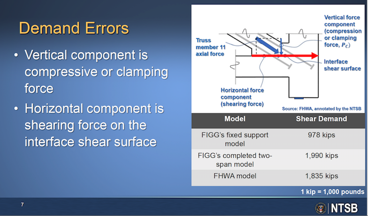
Walsh is a veteran of other prominent NTSB bridge and tunnel investigations. He told an audience in Washington, D.C. last week that FIGG chose the low value for demand on the key node obtained from one of four different models the designers created for the project: A two-dimensional model of the completed two-span bridge; a two-dimensional model of the main-span support during transport; a three-dimensional model of the main span simply supported at the south pier and pylon pier; and a three-dimensional model of the main span fixed support altered to replicate completed condition.
“Despite the completed two-span model generating the largest forces, for reasons unexplained, the FIGG design exclusively used the results for the main span simple and fixed support models,” said Walsh.
Underestimated Shear Interface Demand
The result was an underestimation of shear interface demand at different nodes varying from 41% to 91%, measured in kips, said Walsh.
In an interview for the collapse probe, an NTSB investigator briefly zeroed in on how the design decisions were made. He asked an engineer at FIGG, Manuel Feliciano, to explain how he decided which software to use to model different aspects of the bridge structure. Feliciano answered that he had used a model generated with LUSAS design analysis software to generate the force effects for interface shear calculations.
“For that question about the node design, we rely on the LUSAS model because we thought that will represent -- will have a better representation of that local area versus the LARSA model,” a reference to another type of structural design software.
LUSAS “was more general,” said Feliciano, and its model “had all the PT bars and all the tendons.”
The answer seemed to satisfy the questioner.


