Contractors Defend Work at Troubled Salesforce Transit Center
Transbay Joint Powers Authority alleges steel fabricator caused brittle fractures
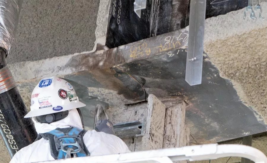
Transbay Joint Powers Authority says a fabricator's failure to grind a weld access hole led to the brittle fractures of the Fremont Street girders at the Salesforce Transit Center. Fabricator says the holes are cuts, not WAHs.
Photo Courtesy of TJPA
The steel subcontractor and the fabricator for the problem bridge-like spans at San Francisco's Salesforce Transit Center are vigorously countering the Transbay Joint Powers Authority's contention that a construction error caused the brittle fractures of the hub’s two built-up plate girders over Fremont Street. They also are registering concerns about the TJPA investigation into the brittle fractures, claiming bias on the part of the public owner.
TJPA shut down the 4.5-block-long bus depot in late September, less than six weeks after it opened, after a ceiling installer noticed a crack in one of the twin parallel tapered girders that span 87 ft over Fremont Street. Work to repair the girders is scheduled to start this month and conclude in June.
There is no announced date for the hub’s reopening. Commuters continue to use the temporary facility constructed for the duration of the transit center construction project.
Few questions have been answered, six months after the hub’s shutdown. Should there be stricter materials requirements regarding fracture toughness for heavy, thick plates and sections? Should there be extra procedures for the review of nonstandard details? Should there be more specific cutting and welding sequences for nonstandard designs, especially for cuts in heavy plates? And should there be better procedures for shop drawing review and approval?
“If you point to the facts and the evidence, it's pretty clear. In another venue, it will be debated.”
– Ron Alameida, TJPA's director of design and construction.
An answer to one big question was provided earlier this month, but some of the parties involved say it is a wrong answer. On March 14, at a TJPA board of directors’ meeting, Ron Alameida, TJPA’s director of design and construction for the transit center, said the cause of the fractures was “most likely” a fabrication problem.
“The evidence seems to land there,” he added. “It has from my view. If you point to the facts and the evidence, it’s pretty clear. In another venue, it will be debated.”
Mark Zabaneh, TJPA’s executive director, says, “It is the responsibility of the contractor to deliver a defect-free product. That clearly did not happen here.”
Looking for quick answers on construction and engineering topics?
Try Ask ENR, our new smart AI search tool.
Ask ENR →
Steel subcontractor Skanska USA Civil West says it is premature to speculate about the causes of the fractures until an independent, third-party evaluation of all potential causes—including the unique design of the girders—is completed.
“TJPA continues to make false statements regarding inspections and the responsibilities and actions of their engineer of record in an attempt to muddy the waters and shield their EOR from well-warranted scrutiny over their handling of the girder design process,” says Skanska.
Zabaneh responds: “The independent review will conclude what transpired, but whatever the conclusion, the public was let down and we intend to hold the responsible party accountable.”
In addition, according to the original independent peer review panel that was formed to oversee the design during the development of the project and recent analysis by LPI, the design of the girders is sound and appropriate, adds Zabaneh.
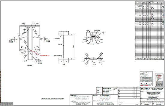 |
| Shop Drawing P537BB, approved as noted, shows MISSING WAH note from the engineer of record, with an arrow pointing to the midsection of the web, at the hanger plate. |
He continues: "We have no information or evidence to date that leads us to doubt the validity or appropriateness of the design. However, if additional facts or new information is presented, that would be considered. The only evidence we have, to date, points toward a failure by the contractor to follow code...."
Identical Twin Girders
The 1.2-million-sq-ft transit center, designed by Pelli Clarke Pelli Architects with executive architect Adamson Associates Inc. and engineer-of-record Thornton Tomasetti Inc. (TT), was built by the Webcor/Obayashi Joint Venture. The Herrick Corp. is the fabricator of the Fremont Street girders and identical twin girders that span First Street, which did not fracture.
The third-floor girders support a rooftop park directly above and the second-floor bus level—via a welded midspan hanger connection—directly below the girder level. The main focus of the controversy are the 2 in. x 4 in. holes cut in the girders’ bottom flanges, one on each side of the web, near the hanger plate.
Alameida’s statements came after Robert S. Vecchio, CEO of TJPA’s independent forensic metallurgist, LPI, presented LPI’s findings that the brittle fractures resulted from the formation of shallow surface microcracks—which developed during thermal cutting of the bottom-flange holes to "allow for welding to be completed” in the area near where the hanger plate passes through a slot in the flange.
The microcracks, on the so-called weld-access-hole radii, became larger pop-in cracks, which likely formed during the full-penetration welding of the ends of the bottom flange plates, at the girder’s midspan. Finally, rapid low-energy fracture of the flanges occurred as the girder was subjected to service loading, says LPI.
First Street girders did not fracture because, unlike for Fremont Street girders, the First Street holes were cut after the girders had been welded, says Vecchio.
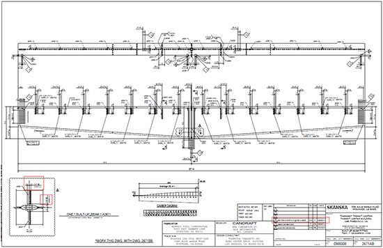 |
| A revised shop drawing shows cuts in the bottom flange of the girder. |
There were other factors necessary for the fractures, he adds. LPI’s testing indicated the presence of a very brittle zone at about mid-depth of the 4-in.-deep flange plates. The low-fracture toughness enabled the fine cracks to form, says LPI. Vecchio added there was nothing deficient in the welds, which passed inspection by TJPA’s inspector, ISI, or in the steel plate, which met specifications, though "barely," he says.
The latest maelstrom, triggered by Alameida’s statements and Vecchio’s root cause report at the March 14 meeting, boils down to a major disagreement over the definition of—and responsibility for—dimensioning and locating the holes that the design team calls “weld access holes” (WAHs) and the construction team calls “hole cuts.”
According to TJPA, Skanska and Herrick, TT first introduced the girder WAH during shop drawing review, by placing a "MISSING WAH" note on the drawing, which it then approved as noted. The note has an arrow pointing to the web in the area thickened by the hanger plate, just above the flange.
Zabaneh says the LPI findings are that the holes at Fremont Street, “were not installed to code in both dimensions and treatment, [meaning] they were not ground to bright metal finish. Per LPI’s conclusion, had the WAH been ground per code, fissures would not have taken place and the girders’ bottom flanges would not have been cracked."
Bob Hazleton, Herrick’s president, says the holes that LPI calls WAHs are not WAHs but are cuts in the flanges. WAHs are located in the web, not the flange, and they were not required to access or complete a weld. In addition, “these holes do not meet the size and shape of a weld access hole, which is why they were not ground or subjected to nondestructive testing,” says Hazleton.
The American Institute of Steel Construction concurs that the holes in question are not WAHs, as dictated in AISC’s Specification for Structural Steel Buildings.
Turning a Deaf Ear
Skanska also is concerned that TJPA is turning a deaf ear to its and Herrick’s experts, who have completed independent finite element analyses of the girder design and extensive residual stress analyses.
“These analyses showed very similar results of high stress levels in the design of the girders and hanger connection where the cracking occurred,” says Skanska. “These high-stress-level concentrations resulted in structural members that were susceptible to failure.
"This a unique and complex design, where a hole in the girder flange accommodates a hanger, thereby reducing the cross-sectional area of the tension flange in very close proximity to the flange weld….It has raised concerns from all corners," says Skanska.
Skanska maintains that in such a high-stress environment, the designer should have mandated certain fabrication processes that would be critical to mitigate such an environment. “This is not only logical, but it is the responsibility of a designer to outline such critical situations in the design documents and mandate such mitigation directives,” says Skanska.
TT has declined to comment until the investigation is complete, except to state the “indisputable” facts, says Bruce Gibbons, TT's managing principal. The holes in the Fremont Street girder flanges were proposed in [a request for information] by the steel subcontractor, for the purpose of executing the welding of the girders, he says. “In that RFI, the holes were described as weld access holes by both the steel subcontractor and engineer, and they were clearly to be executed per AWS D1.1. No concerns or comments regarding the suitability of this detail were raised by the steel subcontractor at the time,” he says.
AISC knows of no other similar hanger details. “We do not believe a detail with a plate girder flange interrupted by a member passing through a hole in it was contemplated in the writing of the requirements for typical design and construction provided in AISC 360,” the Specification for Structural Steel Buildings, says Lawrence F. Kruth, AISC’s vice president of engineering and research. “As a result, there is no standard practice we can point to for it.”
AISC maintains that the designer who chooses to use a novel design or detail must also decide what special requirements, if any, are needed for its design and/or construction. “In our experience, laboratory testing of new ideas is a common way to establish what special requirements are needed, if any,” says Kruth. “This approach is specifically permitted in AISC 360 Section A1, which says, ‘Where conditions are not covered by this Specification, designs are permitted to be based on tests or analysis, subject to the approval of the authority having jurisdiction.’"
Unique Configuration, High Girder Stress
Skanska says it has had several meetings with the TJPA to express its concern over the unique configuration and high stress levels in the girder design, as found by Skanska’s third-party experts. Skanska’s request to present its findings to the TJPA board were denied.
Zabaneh says the board presentations are technical and for the purpose of assuring the directors that the fix is adequate, not to cast blame for the failure. Or, as Alameida said at the March 14 meeting, the presentations are about the “what” not the “why.”
In a letter to TJPA, dated March 20, Herrick registered its concerns about the terminology used for the cuts and the methods selected by TJPA to evaluate the brittle fractures. “TT and LPI repeatedly refer to the flange holes added by TT as weld access holes,” says the letter. “A hole in the flange is not a weld access hole and these specific holes were never required by Herrick to access or complete a weld.”
TJPA’s reply: “Mr. Vecchio accurately described the weld access hole appropriately.”
Skanska and Herrick agree that TJPA should have engaged an independent designer, rather than the structure’s engineer of record, to address the many concerns. “TJPA made the decision to place TT as the entity responsible to investigate analyze and provide recommendations concerning the fractured girders,” says Hazleton, in the March 20 letter. “The selection of an interested party to conduct an evaluation for causation of the fractures is against all rational thinking and contrary to proper procedure of a government entity working on behalf of the public.”
Defending Peer Review Independence
TJPA’s Zabaneh replies, referring to the independent peer review panel created by the region’s Metropolitan Transportation Commission: The panel, which has expertise in steel structures, fracture mechanics and metallurgy, is reviewing steps taken by the TJPA team investigating the causes. Zabaneh says the independent review ensures TJPA has no bias in the investigation.
“We owe the public a transparent, expeditious and independent process and I am confident that what we have laid out here to determine the cause is fair, solicits and considers the feedback of all concerned parties, and is taking all of the facts into consideration."
He continues: “Not everyone is going to like the final results, but I am confident that the process is fair and will ultimately give us the information we need to reopen the center and make sure something like this does not happen again.”
Michael D. Engelhardt, a professor of civil engineering at the University of Texas, Austin, and the chair of the panel, explains that the panel’s charge is to review technical factors contributing to the fractures, “so that we can have a high level of confidence that the repair is appropriate and safe.”
He adds, “It is not our charge to review contract documents to establish culpability of various parties involved in this incident.”
The panel also is not charged with doing independent analysis of the design. The starting point is conditions as they exist in the field. This includes the overall girder design in-place, the fabrication conditions in-place and the material characteristics in-place.
“We are not looking at what aspects of the design, fabrication, and materials did or did not meet the requirements of the construction documents, did or did not meet prevailing codes and standards, did or did not meet the standard of care or best practices, etc.,” says Engelhardt.
Much of the disagreement between TJPA and the contractors has its genesis in a note on Fremont Street shop drawing P537BB, approved as noted by TT. That note initiated a request for information and an instruction to the steel fabricator, through a revised shop drawing P537BB, to cut the holes in the bottom flanges. TT never saw the revised shop drawing, which directed Herrick to make the cuts in the flanges. The revised drawing did not refer to the cuts as WAHs.
Hazleton speculates that if TT had written, “revise and resubmit” on the shop drawing P537BB, the chain of events that led to the fractures may never have happened.
The holes in question were not specified in the original contract documents. “During the shop drawing process, the project’s structural engineer, Thornton Tomasetti, determined the holes were necessary and appropriate and directed that they be cut in the [web of the] girders,” says Skanska.
Herrick's Hazleton adds, “The instructions to the detailer in the original detail on the structural drawings, in the shop-drawing comments, and in the RFI response were all vague, lacking in detail and insufficient to define the engineering intent at a critical location in a critical member. The RFI response appears to be motivated more by a desire to avoid laying the grounds for a change order than by providing information. This could certainly be described as a process breakdown.”
AISC Weighs In On Approvals
Regarding approvals, AISC weighs in. Section 4.4.1 of the AISC Code of Standard Practice says: “Approval, approval subject to corrections noted, and similar approvals of the approval documents shall constitute the following: (a) Confirmation that the fabricator has correctly interpreted the contract documents in the preparation of those submittals. (b) Confirmation that the owner’s designated representative for design has reviewed and approved the connection details shown in the approval documents and submitted in accordance with Section 3.1.1, if applicable. (c) Release by the owner’s designated representatives for design and construction for the fabricator to begin fabrication using the approved submittals.”
Regarding the notation “MISSING WAH,” the fabricator’s actions would depend on the clarity of the notation, says Kruth. “As we understand the situation, it is a question whether this notation was clear for what the fabricator was supposed to do. When a notation is unclear, we would expect the fabricator to request clarification and the structural engineer to clarify.”
TJPA says the note on the shop drawing was a suggestion, not a directive. TJPA’s shop-drawing scenario is that in the drawing review, the designer brought to the contractor’s attention the possible need for a WAH in the web. The designer responded by agreeing with the need for a WAH in the flange, as advised by the contractor. The designer then referred the contractor to the code to properly install the WAH.
“It is the responsibility of the contractor to decide whether they needed a WAH or not and to build it to code," says Zabaneh. WAHs are a means and methods utilized by the contractor, if necessary to facilitate welding, he adds. "They are not directed by the designer or shown on the design drawings."
Skanska Expresses Shock
Skanska’s reply: “Skanska is shocked by TJPA’s assertion that adding the holes in question was intended as a suggestion and not as a directive by the engineer of record. An EOR is not in the practice of making means and methods recommendations on shop drawings.
“The Fremont Street shop drawing was reviewed and approved by Adamson Associates, noting ‘make corrections as noted,’ and subsequently by TT (“approved as noted”). The only note was ‘MISSING WAH’ and an indication of its location. That note was not a question or suggestion, it was a directive – and would have been interpreted as such by anyone with experience in this industry.”
Skanska explains that clarification on TT’s directive was requested by the steel detailer, Candraft, through an RFI, as the EOR did not provide any specific information about the hole and a WAH at the location indicated—in the web where it is thickened by the hanger plate—was not standard.
“The shop-drawing comment is not a question; it points to the hanger and says 'MISSING WAH.' The reviewer may not have understood the detail, which is an indication of the lack of information on the original design drawing,” says Hazleton.
"If the EOR wanted a specific 'cut hole' in the tension flange adjacent to the hanger, we would expect a specific detail like Detail 1 on S1-4202 applicable to the specific situation at the hanger,” he adds. Multiple parties in the communication chain were confused about what the EOR intent really was for this situation.
The Metropolitan Transportation Commission's peer review panel has yet to announce when it will release its final report, but it is not expected before June or July. Engelhardt says he expects the report to contain lessons learned and broad recommendations on issues that the panel believes “should be considered by the industry to avoid this type of failure in the future.”


