Seattle’s Eccentric ‘Book Behemoth’ Shatters Stereotypes
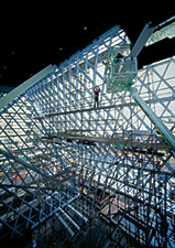
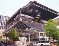 |
| Massing is not arbitrary and reflects the library’s program. (Photo courtesy of Michael Dickter/Magnusson Klemencic Associates) |
Seattle’s 412,000-sq-ft "book bag" has been cheered as outrageous architecture and reviled as architectural outrage. Rem Koolhaas, the Dutch "starchitect" for the $154-million library, reminiscent of a stack of books wrapped in a fishnet, calls the building "obscenely beautiful." But the team plotting the city’s latest page turner–the most gawked at and talked about volume since Frank Gehry’s Experience Music Project down the street–is largely deaf to the cacophony. Their energies are focused on substantially finishing the obscenely eccentric and eight-month-overdue building by March 9.
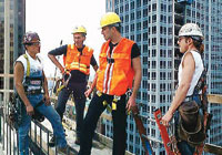 |
| Koolhaas, Ramus (in yellow hats). (Photo courtesy of OMA / LMN) |
The Seattle Central Library has already shattered complacency, as intended. "When something stirs people up, it is doing what it is supposed to do," says Joshua Ramus, Koolhaas’ partner on the job in the New York City office of the Office of Metropolitan Architecture, Rotterdam. Ramus is confident people will like the library "formly," once they have experienced the dramatic interiors.
The job has certainly stirred up the building team, especially for responsibility of "late charges," mostly concerning the diamond-patterned exterior wall. "We are in the process of doing change orders," says Douglas R. Winn, a vice president of Hoffman Construction Co. of Washington, the local general contractor-construction manager.
|
Though there were site-related delays, the crux of the brouhaha is the architectural sleight of hand that makes the building’s "glass" wrapper camouflage its steel seismic grid. In September, a dispute resolution board issued recommendations about change requests that are nonbinding but admissible in court, should litigation follow. "DRB’s analysis is that $8.5 million is in dispute," says Alex Harris, the library’s capital program director.
All parties decline to reveal specifics about the recommendations, including Hoffman’s original "request for equitable adjustment" to the owner on its current $121.4-million contract. But sources indicate the board has divided responsibility for delays among the owner, Hoffman, steel detailer BDS Steel Detailers, Mesa, Ariz., and shoring design-builder Antioch, Calif.-based Drill Tech Drilling & Shoring Inc. The board did not find fault with the curtain wall design-builder Seele LP, Chicago, a subsidiary of a Gersthofen, Germany-based firm; the steel contractor, The Erection Co., Arlington, Wash.; or steel fabricator Canron Construction, Vancouver, B.C., though BDS is a sub to Canron, which is a sub to TEC.
 |
| JACOBS |
The dispute has done little to dampen the spirits of Deborah L. Jacobs, the head librarian considered the project’s visionary. Stressing that construction is continuing without ill will, Jacobs says the important thing is that "the community is falling in love after questioning this strange-looking building."
Among the doubters are those who say the massing appears arbitrary. It isn’t, says the architect. The form is "derived from experiential, contextual relationships," and is a reflection of both the program and how the building will be used.
To create the form, the architect, a joint venture of OMA and the local LMN Architects, literally stacked program-specific building blocks vertically and pulled public-space blocks to the sides to grab views of surroundings such as Mt. Rainier and Elliott Bay. The result is five perched and offset platforms, with grand public spaces in between, all wrapped in glass and steel.
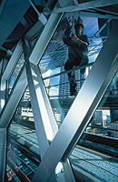
 |
| Reading room’s sloped columns resist seismic grid deflection. (Photo by Michael Goodman for ENR) |
The basement platform, level zero, is for parking and mechanical space. The two-level staff platform above also contains the "kids" room and auditorium. The one-level "living room" is at street level, along the west side. It is topped by the one-level assembly platform, containing meeting rooms. The high-ceiling "mixing chamber," which contains the high-tech media, comes next topped by the four-level books platform, with its innovative book spiral. The high-ceiling reading room overlooks the books platform. The one-story library headquarters platform caps the building. ![]() Click here to view diagrams
Click here to view diagrams
Similar to a parking garage ramp, the 6° book spiral creates a 200-ft-long accessible and continuous "run" for the nonfiction collection, classified under the 000-999 Dewey Decimal System. The ramp has been designed to hold 60% more books than it will have on opening day, in an attempt to avoid having to split the growing collection into different rooms as time goes by.
The ramp created "warped" surfaces on the sloped steel grids above and below it. But the almost imperceptible warp was accomplished without any curved elements, unlike the "swoopy" EMP, say those involved with both buildings. "While EMP oozes complexity," says Robert Vincent, Hoffman’s project manager, "the library might seem more simply crafted." It’s not. Library geometry is more exacting, tolerances are tighter and EMP’s curves are "far more forgiving" than the library’s straight lines, says Vincent.
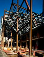
 |
| CANTED Sloped truss supports eliminate transfer girders. (Photo by Lara Swimmer Photography / Hoffman Construction) |
The structural engineer agrees. "The library is much more irregular," says Jon D. Magnusson, chairman-CEO of Magnusson Klemencic Associates, Seattle. Even the seismic grid, which uses the same rolled shape throughout, has variations due to spans and different edge conditions. And thanks to offsets and the architect’s wish to minimize columns and transfer girders, no columns line up in plan. There are only 20 true vertical columns. Designing the frame became an exercise in connecting the dots, says Jay Taylor, MKA’s project manager.
The building is framed in structural concrete from the spread footing foundations, 10 ft below the west grade, to level three, which is at grade on the east. Above, the structure is steel. A mat supports a 213-ft-tall, expressed concrete core, 65 x 44 ft in plan, in the southwest quadrant of the footprint. The core carries gravity loads but resists minimal lateral forces. A 28-ft-wide footing supports two concrete shear walls and a concrete column in the northwest corner of the concrete substructure.
Every platform column around the perimeter is raked and architecturally expressed. Some concrete columns also are skewed. ![]() Click here to view diagrams.
Click here to view diagrams.
Each offset platform box has a perimeter steel truss, on either two or four sides, that matches its story height. The headquarters platform cantilevers as much as 28 ft on each of all four sides. The books platform cantilevers at each of the four corners beyond the sloped column. The assembly platform is hung on the north and the west sides from interior cantilevered trusses.
Sloping columns minimize story height by eliminating girders, but they weigh nearly twice as much and create thrust. In the steel frame, trusses in the plane of the floor diaphragm drag thrust back to the core or to an opposing column. In substructure slabs, extra reinforcing steel takes the thrust.
The three-story belt truss for the 200 x 176-ft books platform is the hardest-working, says the engineer. The south truss is supported by the biggest column, a 3-ft-square box column made of 23/4-in.-thick plate. The column lands on top of the substructure.
Ramp slabs in the north and center sections are sloped east to west but the book shelves, accessible off the ramp, will be on flat-topped "steps" created by a topping slab.
The grid knits the platforms together, preventing them from tipping over. Made from 12-in.-deep wide-flange members, the grid works like a giant braced frame, collecting seismic forces from each platform, carrying them across the grid to the next platform and ultimately to the concrete base. The building is designed for site-specific ground motions based on an earthquake with a 500-year return period.
Diamonds are 4 ft on a side. The grid size, set during schematic design in a collaboration with OMA/LMN, Hoffman, MKA and structural engineers from Arup’s London and Los Angeles offices, was determined by the largest glass panel that could span without need for a girt system to attach it to the grid. This dramatically reduced costs.
Diamonds are assembled into seismic panels, oriented from 21° to 45° from horizontal and up to 84 ft in length. Three stiffening solutions control panel deflection due to its own weight, curtain wall weight and wind loads. These are "intervention" columns, strongbacks and steel gravity columns in the plane of the grid. For example, five sloped, expressed interventions in the reading room limit vertical deflection. Strongbacks, mostly mid-panel, create amoeba shapes that follow stress patterns. Amoebas combined with interventions act like drop panels in flat-slab framing. Amoebas alone provide more depth for longer spans.
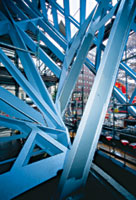
 |
| To avoid fireproofing, designers had to keep seismic grid from accepting gravity loads. (Photo by Michael Goodman for ENR) |
The architect wanted the seismic grid exposed on the interior, for appearance and to save on fireproofing costs. Under the Seattle code, steel does not have to be fireproofed if it does not take gravity loads.
To satisfy that, MKA designed the primary frame to stand on its own, without benefit from the seismic grid. Vertical slot connections between the grid and the gravity frame at the tops of sloped sections keep gravity loads out of the grid.
Halfway through the 18-month approval process, 9/ll occurred. "The fire department became much more wary" and increased exiting load requirements, says Sam Miller, LMN project manager.
The building is fully sprinklered. But that left the issue of smoke control. Under the fire code, interior volumes, such as the mixing chamber and living room, are considered one giant atrium because they are open to one another through overlooks and a 140-ft-tall skylight. The code called for 800,000 cfm of exhaust, which would have been costly and required a "huge" number of louvers for makeup air, says Miller.
A computational fluid dynamics computer model for smoke flow, created by the San Francisco office of fire protection engineer Arup Fire, was used to convince officials that only 275,000 cfm was needed. The CFD graphic gave the fire department its first understanding of how the building worked, says Miller.
Hoffman was awarded the job in June 2000, as EMP was winding down. During preconstruction, the focus was on constructibility and the budget. In early January 2001, Hoffman put some numbers on the table that "floored everybody," says Vincent. The estimate had ballooned by $20 million.
Through value engineering, "we were able to bring the project in on budget," says Vincent, without any significant loss of design intent and with program improvements. For example, the team sliced $2 million by combining the top two levels into one, thus lowering the profile.
 |
| Seismic grid grows up around temporary steel. Photo by Lara Swimmer Photography / Hoffman Construction) |
Because the job was fast-tracked, the library applied for a concrete permit before structural steel design was complete. But footings for steel falsework had to be part of the concrete package. For this, and to attract more bidders, Hoffman hired MKA to do a preliminary design of temporary steel and a steel erection sequence. "That’s really rare," says Dale Stenning, Hoffman’s senior project engineer. Bidders could alter the erection sequence but not footing location or size.
Hoffman got a notice to proceed on Sept. 6, 2001, after the library cleared the site. The only remaining element of the old building was the 43-ft-deep east foundation wall. In December, when crews started digging to extend it down 20 ft, the wall started moving, eventually sinking up to 1 in. and moving into the site as much as 41/4 in. Hoffman called a "big time out" on Jan. 5, which lasted 28 days, so Drill Tech could strengthen its soil-nail shoring system and install a "more-aggressive" drainage system to relieve water pressure on the wall.
Structural excavation and footings began in February. But "unforeseen, inconsistent" soil conditions made overexcavation necessary to replace unsuitable bearing material with good soil. That ate up 20 more workdays. If not for work-arounds, "we probably would have lost another three weeks," says Winn.
Steel erection was slated to begin on Aug. 9, 2002, but did not start until Dec. 9, 2002. If not for accelerated fabrication, the job could have been "well over a month later," says Martin Bache, fabricator Canron’s contracts manager. "We worked hand to mouth to supply the jobsite."
 |
| Can’t tell the structure from the glass curtain wall. (Photo by Michael Goodman for ENR) |
The decision to design the wrapper first and then align the seismic grid perfectly behind it meant the steel detailer had to know the thickness of the glass curtain wall to detail the grid. The detailer did not receive that information on schedule. Responsibility for that is one of the main issues in the dispute over the schedule.
Detailer Don Engler, BDS’s vice president of international operations, thinks starting with the glass and working back to the structure "is a big mistake." But once that’s done, he thinks it is imperative for the contractor to allow enough time for all "predecessor activities," which he says it didn’t.
No one disputes Hoffman’s contract requirement to produce a three-dimensional wire-frame model of the steel centerline geometries for the detailer. Many dispute how it was fulfilled.
Seele President Thomas Geissler says the dispute stems from a "misunderstanding." Seele didn’t have a contractual obligation to give its 3-D model to the steel detailer, though Hoffman kept asking for it. Seele ultimately gave the model to Hoffman, with a liability waiver.
Detailing was supposed to begin in February 2002. Engler claims BDS started receiving "flawed" models that April. Engler claims it "finally" got all the information by that September. The engineer says BDS received the final wire frame in June and received marked-up fold line details after that, until September.
Once the clog was undone, the steel went smoothly. Primary steel was erected on 360 tons of falsework and in a certain order because of construction loading constraints and cantilevers. There were six shore lines, mostly for the books and assembly platforms.
To reduce the unbraced length of falsework as tall as 75 ft, crews gang-braced each line using a horizontal brace mid-height and tied off the brace at its ends only. Certain falsework had to be positioned to allow the seismic grid to be erected around it. And falsework design required consideration of both steel and slab weight because certain slabs, needed for stability, would be poured before deshoring.
TEC crews erected steel on all four sides concurrently. When the first platform was framed, crews started the seismic grid’s underslung sections. In March and April, crews began unloading the four lines supporting the books platform in a synchronized operation. Because lines were ganged, falsework could not be removed one by one. Instead, TEC worked out a method to unload falsework, from the middle toward the corners, through localized yielding of the webs induced by torching the flanges at the base. The goal was to engage key gravity elements in a certain order to minimize twisting. To avoid transferring gravity loads into the seismic grid, the final grid-to-platform connection was not made until the platform had deflected under its own weight.
Steel erection went "incredibly well," says Derek Beaman, MKA’s project engineer, with very few fit-up problems. The same goes for the 130,000-sq-ft curtain wall, even though 3,377 of its nearly 10,000 diamonds are odd shapes.
The warped surfaces of the cladding were formed with lines, straight in one direction and segmented in the other, to create the curvature. Seele designed a 5-in.-long aluminum spacer that fixes the I-shaped mullions directly to the grid’s wide flanges at 8-ft intervals. The spacer, with concealed fasteners, allows steel to be as much as 1/2 in. out of plane.
 |
| Five members join at different angles. (Photo by Michael Goodman for ENR) |
Crews are installing the skin piece by piece, starting with aluminum profiles and extrusions. Next comes a silicone gasket for waterproofing, followed by glass. An exterior pressure plate caps the mullions. Gutters and closure panels at fold lines between faces follow. In the worst condition, five gutters join at different angles. "This was a piece of 3-D engineering never done before," says Geissler. ![]() Click here to view diagram.
Click here to view diagram.
Panels are either double or triple glazed. Triple-glazed units have an outer cavity containing a suspended, stretched metal mesh for solar shading, like a micro-louver. The inner cavity contains krypton gas.
The skin was prefabricated at Seele’s plant in Germany. Using a computer program to keep track, Seele labeled and shipped the pieces to Seattle. Curtain wall installation, 80% complete, is to be finished at the end of January. "We saved eight weeks" off a 39-week installation, says Geissler, using a bigger crew, overtime, resequencing and overlapping work.
Glass goes in from the top down instead of bottom up, because work-platform supports penetrate the lower grid.
Geissler says about 30% of grid bolt holes are out of tolerance. This is handled by a spacer that could take steel up to 1 in. out of tolerance.
Installers are averaging 450 sq ft per day, up from 215 at the start. "There was a big learning curve," says Geissler, who adds that Seele had to be "extremely effective" to make money on the $19-million contract.
Librarian Jacobs says the excitement among her 300-person staff is building as the planned mid-spring opening nears. "I continue to get goose bumps when I see the building," says Jacobs, who feels it is already the heart of the city.