Panel Design Plan Streamlines Installation on London's Elizabeth Line
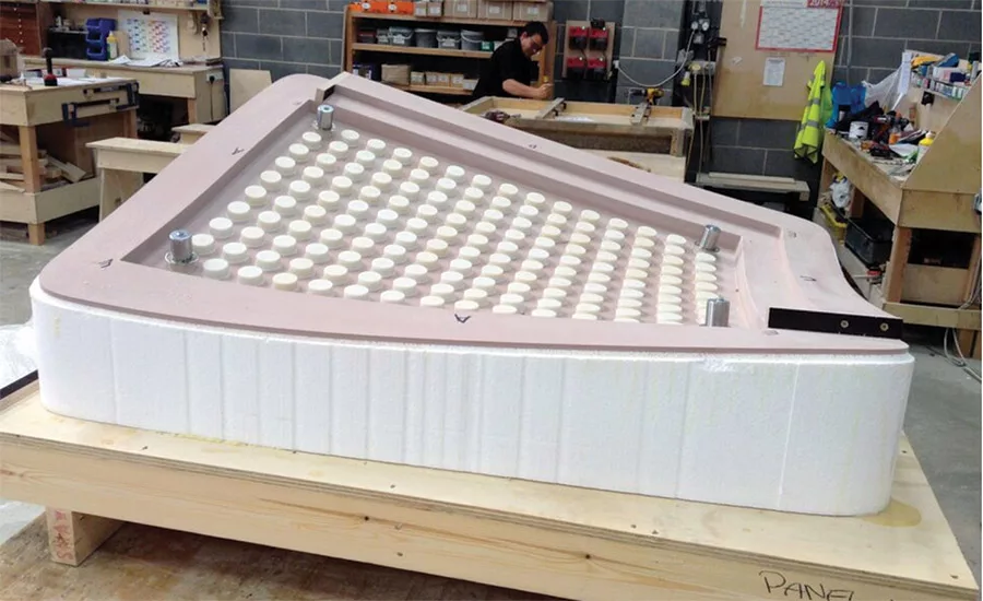
Thousands of glass-reinforced concrete panels were installed on concrete-lined tunnels of varying geometries, requiring only two-person crews rather than heavy equipment.
Rendering courtesy of Bryden Wood
T he 100-km, $19-billion Elizabeth rail line opened in London last month after more than a decade of construction. Teams used a digital workflow to install over 27,000 cladding panels in three of the new stations, reducing needed weight and improving efficiency.
“The digital workflow on this project meant we were able to reach new levels of efficiency and accuracy in the production of the panels,” says Matthew Luhrs, general manager with contractor GRCUK, now part of Laing O’Rourke, which held the contracts for stations at Liverpool Street, Tottenham Court Road and Custom House. “Software typically used in manufacturing was brought into the project to allow us to calculate the exact size and shape each panel needed to be to meet technical standards while fitting the complex geometry of the tunnels.”

3D modeling and point cloud scans eliminated need for fabrication drawings.
Photo courtesy of Bryden Wood
Designer Bryden Wood developed the digital workflow for Tottenham and Liverpool stations as well as the station at Whitechapel, which was built by a joint venture of Balfour Beatty Civil Engineering, Morgan Sindall and Vinci Construction. The overall design included 32,000 sq m of glass fiber-reinforced concrete panels, 23,000 molds, 3.7 million acoustic holes, 36 double-curving junctions, and 6 double-curving “trumpeted” swept openings, says Jaimie Johnston, Bryden Wood board director.
“The tunnels were made by drilling through the ground and spraying a cement mixture onto the walls to stabilize them as they were excavated,” Johnston notes. “So, the walls wavered along their designed route by a significant amount.”
The design called for installing a single rail along the walls, precisely positioned with a laser, and another along the platform level. “This meant we could ignore the tunnel lining and completely control the environment through these two fixed points,” says Johnston. “This greatly reduced the number of fixing bolts we needed and allowed us to use a folding system to install a simplified fixing grid that unfolded between these two rails. The cladding installation was therefore independent of the geometry of the sprayed concrete tunnels. This meant we were working at zero tolerance.” Typically, there would be a tolerance of plus-or-minus 10mm to 20 mm.

3D modeling and point cloud scans eliminated need for fabrication drawings.
Rendering courtesy of Bryden Wood
Designers built 3D models in digital formats fabricators can use, eliminating fabrication drawings. The panels were made to specifications based on the tunnel geometry. Point-cloud scans of station interiors were developed with Autodesk and Solidworks. “In the Solidworks model, every nut, bolt, screw and washer was included,” says Johnston.
The design resulted in a 58% reduction in the overall weight of the cladding and support structure, allowing for two-person assembly crews. Panel thickness was reduced from 25mm to 12.5mm. Total quantity of parts was reduced by 46%. Glass-reinforced concrete was also utilized in some structural arches within the cladding system rather than steel, Johnston adds. “We used large molds to create these self-supporting arches that tied back into the wall at as few points as possible while also allowing for movement in the tunnel over time.”
“It was a feat of tech-led engineering that was pioneering when we used it, and will be for some time yet,” Luhrs says.
Looking for quick answers on construction and engineering topics?
Try Ask ENR, our new smart AI search tool.
Ask ENR →


