Panel's Review of Transit Center's Fractured Girders Draws Heated Reactions
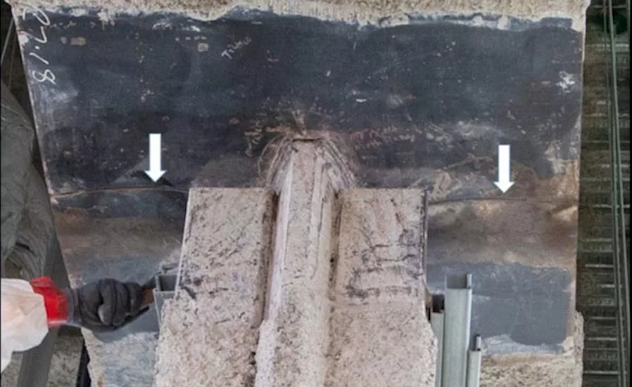
A failed girder at the Salesforce Transit Center in San Francisco. The fracture in the 4-in.-thick bottom flange of the girder, shown from the underside of the flange at the midspan, is near where a hanger slots through the flange to pick up a bus deck below. Photo Courtesy TJPA/MTC Peer Review Panel
The Metropolitan Transportation Commission's independent expert panel that reviewed the 2018 brittle fractures in twin built-up plate girders at San Francisco's Salesforce Transit Center—and made recommendations for changes to steel standards and specifications—was not charged with establishing culpability. The 1.2-million-sq-ft hub, owned by the Transbay Joint Powers Authority, reopened last July 1 after a nine-month closure triggered by the girder failures.
The MTC convened the seven-person expert panel in October 2018 for several reasons, among them to review the failure hypothesis in the report of TJPA's forensic engineer-metallurgist, LPI Inc. But the MTC panel’s scope did not include an independent analysis of the cause of the failure or the assignment of liability.
The Transbay Joint Powers Authority maintains the brittle fractures in twin girders at the Salesforce Transit Center are "a fabrication issue." TJPA continues to hold the steel fabricator responsible.
“We did not draw our own conclusions," but rather reviewed the work to establish the cause [previously] done by the Transbay Joint Powers Authority (TJPA), its project team and its investigating consultants, says Michael Engelhardt, an engineering professor at the University of Texas at Austin, who chaired the MTC panel.
The panel's review also did not include whether the framing in place at the time of the fractures satisfied all requirements of the contract documents, design intent or the standard of care expected in the design and construction of a major structure. And the panel’s scope did not include application and interpretation of the governing standards and specifications in the execution of the design, fabrication and construction.
“The focus was on the technical factors,” says Engelhardt.
John Bowles, the just-retired Webcor executive who led the hub project for the general contractor, the Webcor/Obayashi Joint Venture, says he is “disappointed the panel’s scope of work did not include an assessment of fault.”
Bowles, currently a Webcor consultant still involved with the transit center, was also surprised, in 2018, that TJPA hired Thornton Tomasetti, the hub's engineer of record, to investigate the failures and review its own design, rather than a neutral party.
Looking for quick answers on construction and engineering topics?
Try Ask ENR, our new smart AI search tool.
Ask ENR →
Only time will tell whether the recommendations of the panel's final report, issued Feb. 27, will have an impact on future projects with heavy plate girders. But even without finger-pointing, the report has fueled the ongoing disagreement over responsibility for the transit center's brittle fractures.
In reaction to the panel's recommendations, TJPA says the steel fabricator, not standards, codes and specifications, is still solely at fault for the failure of the tapered girders' bottom flanges. TJPA “maintains this is a fabrication issue and we continue to hold the contractor responsible,” says Christine Falvey, a TJPA spokesperson and director of communications for the City and County of San Francisco.
TJPA “supports the industry in their efforts to strengthen building codes to improve the delivery of infrastructure projects in the future," says Falvey. "That said, the proposed code changes recommended by the Metropolitan Transportation Commission’s peer review committee are not relevant with respect to the underlying cause of the cracked steel girders at the transit center."
She continues, saying that “during fabrication, the design team noted missing weld access holes on the bottom flange of the girders in question. As a result, the fabricator was directed to install weld access holes at various locations in accordance with the requirements of [the American Welding Society's] AWS D1.1."
"If the fabricator had complied with the requirements the subsequent fractures would not have occurred," Falvey says.
 |
|
The connection at the midspan of the tapered built-up plate girder, including the secondary slots where the fractures started, pictured before the failure. Photo Courtesy TJPA/MTC Peer Review Panel |
Bob Hazleton, president of Herrick Corp., which fabricated the girders in question under contract to the transit hub’s steel contractor, Skanska USA Civil West, disagrees.
“Christine Falvey is misinformed,” he says. “Herrick fabricated these girders in accordance with AWS D1.1 and still the fractures occurred, which is why the peer review panel has suggested a review of codes and standards," he continues.
In addition, the American Institute of Steel Construction's steel specification, AISC 360, supersedes AWS D1.1 when it comes to weld access holes, says Hazleton. In any case, TJPA's "own specification says they are responsible for the inspection of cuts, copes and weld access holes,” he adds.
Hazleton maintains that TJPA's design team did not properly detail the failed girder connection. "If you had to rely on the contract documents alone, the detail was insufficient to build the girder," he says.
He adds that the contract documents should not only have been fully detailed, they should have included a sequence for assembly and welding. "It wasn't a standard detail," he says.
Thornton Tomasetti disagrees, maintaining the steel contractor is responsible. "No concerns or comments regarding the suitability of this detail were raised by the steel subcontractor at the time," says Bruce Gibbons, TT's managing principal for the hub.
Robert Vecchio, LPI's chief executive, says several factors, including low-fracture toughness of the 4-in.-thick plate at half depth, contributed to the brittle fractures at the transit center, but he claims the failures “could have been avoided if the steel fabricator followed the current codes and known industry practices."
The scope of the MTC panel also included the impact of the fractures on adjacent elements and the sampling and testing plan for the fractured material, also carried out by LPI. The panel was also convened to search for other susceptible areas in the transit hub and to review TJPA’s fatigue assessment plan.
Other members of the MTC panel, which has completed its work, were John Fisher, a professor emeritus from Lehigh University; Brian Kozy of the Federal Highway Administration; Thomas Sabol of Englekirk Structural Engineers; Robert Shaw of the Steel Structures Technology Center; William Mohr of EWI; and the MTC’s Stephen Wolf, who managed the panel.
Bus Service
The 4.5-block-long transit hub, with its rooftop park, opened for bus service in mid-August 2018. The building was designed by Pelli Clarke Pelli Architects.
Each of the fractured twin tapered girders spans about 87 ft across Fremont. They help support the rooftop park directly above and pick up a second-floor bus deck below. Each girder picks up the bus deck via a hanger plate that thickens the web at its 8-ft-deep midspan and slots through the bottom flange. The top flange is horizontal but each half of the 4-in.-thick bottom flange is inclined, creating a shallow V. That creates the taper, which reduces the depth of the girder from 8 ft at midspan to 5 ft at each end.
A pair of girders, nearly identical to the Fremont girders, span First Street nearby. They did not fracture.
Both systems of twin tapered girders are part of the gravity load-resisting system of the structure. They are not part of the seismic load-resisting system.
On Sept. 25, 2018, Santiago Carrillo, working for Southwest Specialty Contractor, discovered the flange fracture while installing a drop ceiling under the Fremont Street girders. TJPA shut down the facility the same day.
Herrick installed shoring, which was removed after the Fremont girders were repaired and the First Street girders were strengthened. Both repairs used a bolted splint-like design by Thornton Tomasetti, that called for a higher grade of steel than in the original flanges. The depot reopened July 1, after a review of the entire structure.
Ongoing Dispute
A dispute is ongoing that includes issues that predate the fractures. In October 2018, WO filed a complaint against TJPA alleging breach of contract. The suit seeks more than $150 million in extras on WO’s $994,517,600 contract. TJPA later countersued.
TJPA's direct costs related to the temporary closure total $7.5 million, says Falvey. This primarily includes the building-wide review, the related redesign, inspections and the peer review. TJPA declines to comment further, however, due to the litigation.
Webcor's Bowles says a mediation with the several insurance carriers is likely to begin in the fourth quarter of this year. There is more than enough insurance to cover all the brittle-fracture-related costs, including the $15-million cost of the repairs and emergency shoring, says Bowles.
Was the Code Wrong?
All agree, including LPI Inc., that Herrick provided material, purchased from ArcelorMittal USA, that complied with the project specifications. But “material of much higher yield strength and toughness was available and the design team did not specify it for this critical member,” Hazleton says. “It was allowed by code, so a decision needs to be made. ‘Was the code wrong or the design team that specified the material wrong?’”
Hazleton also points out that the design team selected a much higher grade of material for the repair of the flanges, when it could have specified the higher grade initially.
For each girder, the hanger plate is 18-in.-wide, 4-in.-thick and more than 10 ft long. The hanger is welded to the adjoining 1.5-in.-thick web plates by complete joint penetration (CJP) groove welds. The hanger starts at the bottom side of the top flange and extends below the girder about 2.5 ft.
There are fillet welds between the hanger and the bottom side of the top flange, and between the hanger plate and the bottom side of the bottom flange. Angles are bolted to the lower protruding portion of the hanger beneath the bottom flange. The angles connect the hanger to a wide-flange member that extends down to the bus deck.
The 4-in.-thick bottom-flange plates that meet at the midspan are connected to each other by a CJP weld.
The MTC panel concurs with LPI's basic failure hypothesis, with some caveats. LPI made "reasonable assumptions, but they were assumptions," says Michael Engelhardt, MTC panel chair. Unknowns will remain, such as the date and time of the fractures, the temperature and live load at the time and stresses imposed when the slab was cast.
At midspan, each bottom flange has three thermally cut slots. The largest slot, which the MTC panel calls the primary slot, conforms to the shape of the hanger, allowing it to pass through. Two additional secondary slots were cut into the bottom flange, on either side of the primary slot, in the region of the CJP weld. These slots are about 5 in. in length and 2 in. in width. In the LPI report, the slots are called weld access holes (WAHs).
The transit center was designed for static loading, not dynamic loading. "These girders are not driven by fatigue," says Thornton Tomasetti's Gibbons. The loads from the buses were so small relative to the loads from the rooftop park, he adds.
Failure Hypothesis
In its final report, the MTC panel concurs with LPI's basic failure hypothesis, with some caveats. To come up with its hypothesis, LPI made “reasonable assumptions, but they were assumptions,” says Engelhardt.
There are some unknowns that will remain unknowns, such as the date and time of the fractures, the temperature and the live load at the time of the failure and the stresses when the slab was cast, he adds.
The fractures resulted from low-fracture toughness deep inside the 4-in.-thick flange plates, combined with normal microcracks from thermal cutting, the welding sequence and stress levels. Stress in the flange that initiated the brittle fracture was a combination of residual stresses from the welding of the CJP groove weld in the bottom flange and stresses from loads on the girders after erection, with a stress concentration effect caused by the reentrant corner of the secondary slot, says the MTC panel.
Thermal cutting of secondary slots in the girder bottom flange produced microcracks in the radii of the reentrant corners of the secondary slots at mid-thickness of the bottom flange plate. Some later became larger “pop-in” cracks at the mid-thickness of the bottom flange plate, with a depth on the order of 3/8-in., says the panel.
“These pop-in cracks likely occurred due to tensile stresses generated by weld area shrinkage from production of the complete joint penetration weld in the bottom flange,” says the MTC panel.
Sometime after the girders were erected, brittle fracture of the bottom flange occurred, initiating at the pop-in crack in the radius of the secondary slot at midspan of the bottom flange plate and extending to the outer edge of the flange, says the panel. “The girder fractures were facilitated by the significantly low fracture toughness of the steel near mid-thickness of the 4-in.-thick bottom flange.”
WAH Definition
As a result of the review, the MTC panel recommends that AISC reevaluate the standard quarter-down sampling location for thick-plate quality testing for fracture toughness and the number of test samples required. Also, the group is asking AISC to clarify the definition of weld access hole, reconsider the adequacy of grinding requirements and develop a risk-assessment approach for brittle fracture conditions.
In response, AISC quickly formed a task force to determine if any changes need to be made to the AISC Steel Specification. The group also will decide whether any guidance should be added to the AISC Steel Manual.
Lincoln Electric's Duane Miller, a welding expert, is the chair of the AISC group, which is working pro bono. Other members are Rob Connor, from Purdue University; Jim Fisher, a past chair of the AISC specification committee; Chris Hewitt of Simpson Gumpertz & Heger; Larry Muir, a consultant; Tom Murray, of Virginia Tech; Tom Schlafly, representing AISC; Jim Schoen, of Nucor-Yamato Steel; and AISC's Eric Bolin, the group's secretary.
No timeline has been set for the group's recommendations, says Lawrence F. Kruth, AISC’s vice president of engineering and research. He adds that AISC is unable to comment on the MTC panel’s recommendations until the AISC group completes its work.
Brittle Fracture is Rare
Though AISC is not commenting on specific panel recommendations, Kruth does offer the following: “Brittle fracture in steel structures is rare. When it does occur, it is most likely due to the details that are used. Material toughness and loading also affect it, but even the toughest material at the lowest loading can be compromised with a bad detail.”
 |
|
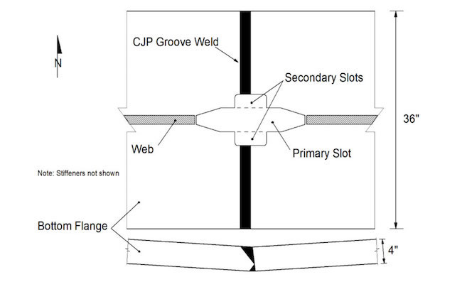
A view of the nonstandard connection, showing the primary slot for the hanger in the girder's bottom flange and the secondary slots, added based on a change order, where the cracks initiated. Drawing Courtesy TJPA/MTC Peer Review Panel |
Kruth refers to Chapter 13 of the AISC Design Guide 21 Welded Connections – A Primer for Engineers by Duane Miller, which covers how to prevent brittle fracture: “For most building applications, the limit state of fracture is not a principal concern because it is not typically the controlling limit state.
"There are many reasons why this is the case," the book continues. "The steel in most buildings in service is relatively warm, service loads create strain rates that are essentially static, the number of full design stress cycles is typically low, codes limit the severity of stress raisers, buildings normally have significant redundancy, and the typical fracture toughness of steels used in building construction is adequate even when fracture toughness levels are not specified."
The rest of the chapter covers the conditions that do merit consideration and solutions that provide acceptable combinations of proper detailing, material toughness and loading, says Kruth.
He adds that much has been published related to proper detailing—especially at connections—to avoid fractures in steel. Beyond Miller’s AISC design guide, there is also Fracture and Fatigue Control in Steel Structures by Stan Rolfe and John Barsom. “It has been the seminal reference on the topic since it was first published in the 1970s,” Kruth says.
Critical Structural Applications
In the view of the MTC panel's authors, materials of such low-fracture toughness substantially increase the likelihood of brittle fracture and should not be allowed in critical structural applications for details susceptible to brittle fracture, such as those described in Section A3.1d. of AISC 360.
The authors suggest that AISC 360 reevaluate the standard quarter-thickness sampling location for Chary V-notch testing, considering the very- low mid-thickness CVN values found in the fractured flanges. Serious consideration should be given to changing the required sampling location to mid-thickness for details that may be susceptible to brittle fracture. This is analogous to the AISC requirement for special CVN testing of the core area of jumbo rolled sections, say the authors.
Thornton Tomasetti's Gibbons agrees with the recommendation. "The steel was less tough than even similar plate in other parts of the facility," he says. "Requirements for testing should change for thick plates," he adds.
LPI's Vecchio also supports the MTC panel's recommendations, "to ensure past mistakes are not repeated." He is particularly interested in changes to the requirements for fracture toughness testing.
The CVN test of 20 ft-lb at 70 F should be performed near mid-thickness to ensure the 20 ft-lb at 70 F requirement is met throughout metal plate of 2 in. or greater in thickness, he says.
The panel also advises AISC to provide guidance on establishing CVN test temperatures for structures exposed to ambient temperatures, either during construction and/or during the service life of the structure.
A factor contributing to the brittle fractures was the hard layer of martensitic material at the surface of the secondary slots that formed because of the thermal cutting of the slots. Microcracks formed at the radii of the reentrant corners of the secondary slots due to a stress concentration effect.
The microcracks subsequently developed into larger pop-in cracks that initiated the fractures. This condition was exacerbated by the proximity of the reentrant corners of the secondary slots to the CJP groove weld in the flange, the report continues.
Both AISC 360 and the American Welding Society Structural Welding Code-Steel (AWS D1.1) provide some guidance on when grinding is required for thermally cut surfaces in thick materials to remove hard surface layers and microcracks. More specifically, these standards require thermally cut surfaces of weld access holes in thick materials to be ground to bright metal, says the report. Further, these standards provide dimensional requirements for weld access holes to further minimize the risk of brittle fracture.
Major Disagreement on Weld Access Holes
There is major disagreement, especially between Thornton Tomasetti and Herrick, about whether the secondary slots qualify as “weld access holes” and, as such, whether they were subject to the dimensional requirements and surface finish and grinding requirements of AISC 360 and AWS D1.1. The review panel purposely did not use the WAH terminology, which LPI used in its report. Instead, the panel called the cuts “secondary slots.”
The addition of the secondary slot was a design decision, says Herrick's Hazleton.
Stating that dimensioning of the secondary slot was about means and methods, while calling it a weld access hole, is evidence that the designers are "ignorant" of the code, he says.
It appears the WAH terminology, regarding the girders, was first introduced on shop drawing P537BB, dated Sept. 24, 2014. Thornton Tomasetti noted “Missing WAH,” with an arrow pointing to the midspan of the web, just above the bottom flange. On. Dec. 2, 2014, Skanska issued Request for Information 978 to Webcor.
The note on the RFI, presumably offered by steel detailer Candraft working for Skanska, said: “It is not clear what is meant by this approval comment. A WAH is not required in the 4” vertical plate but it seems WAHs are required where the CJP weld for the 4” flange plates terminates at the 4” vertical plate.”
The RFI then asked for the dimensions for the WAHs, if required. Thornton Tomasetti's response was: "We disagree with the reason for the request: insufficent information. We categorize this RFI as clarification on means and methods."
Revised Shop Drawings
Hazleton says the revised shop drawings Herrick received did not call the slots WAHs. It called them cuts. And he says the cuts, aka secondary slots, are not WAHs based on their shape, smaller size and flange location, and that they were not needed for welding. WAHs are typically in webs, not flanges, says AISC.
Hazleton also says that a weld access hole, much larger by code than the secondary slot, if completed by the fabricator, would not have contributed to completing the joint and it would have removed an amount of material that would have compromised the hanger.
"It does not appear Thornton Tomasetti reviewed the revised shop drawings," says Hazleton.
"The characteristics of a weld access hole are codified," he adds. "The slots do not meet any of those characteristics so grinding was not required. Thornton Tomasetti provided notes for grinding where required in numerous places in the design documents. None were provided for this critical connection."
The job’s timeline and fabrication sequence are important to understand why the First Street girders, which also have secondary slots, did not fracture, says Engelhardt. Others involved agree.
In March 2015, an inspector armed with RFI 978 directed Herrick to cut holes into the already-fabricated First Street girders. Herrick refused until it received a revised shop drawing from Skanska, called P151, dated April 4, 2015, says Hazleton. P151 shows “cuts” in the bottom flanges.
"We built the First Street girders in accordance with a set of approved shop drawings and put a cut in after receiving a revised shop drawing," says Hazleton.
For the Fremont girders, not yet completed in April 2015, Herrick used a cutting machine to make the secondary slots before butt-welding the two bottom-flange plates where they meet at the midspan. Shrinkage from cooling likely increased the cracks.
Thornton Tomasetti's Gibbons maintains the secondary slots should have been ground. “There were three fabricators on the project and there were no other areas found where we had thermal cuts in thick plates that were not ground,” he says, adding the cuts [elsewhere] were not necessarily WAHs.
“Some fabricators [grind] as a matter of routine when there is a cope or some other type of cut to a radius,” says Gibbons. “Some think it was good practice. Let’s just make it more clear in AISC 360 what we are expecting. Clearly some clarification is required.”
In response, Hazleton says, copes require grinding per AWS D1.1 Clause 5.17, the same as weld access holes.
The picture provided in AWS for a cope is the same as that shown for weld access holes in one important aspect; both are “shown in the web and only in the web,” says Hazleton. “Bruce is extending that requirement to a cut in the flange because it is the only case they have for saying the surface should have been ground. TT provided notes for cuts in the flange in other areas of the contract documents, but not these cuts,” he adds.
 |
|
A broader view of one of the two girders that later sustained fractures at the Salesforce Transit Center in San Francisco. The hanger slots through the bottom flange and is bolted to a wide-flange member. Photo Courtesy TJPA/MTC Peer Review Panel |
To try to clear up the issue of WAHs and their treatment, the panel’s recommendation is that AISC 360 and AWS D1.1 clarify the definition of the term WAH to include only those details required to accommodate welding as illustrated in the commentary of AISC 360 and as illustrated in AWS D1.1.
Where needed, these standards also should provide requirements or guidance on the preferred sequence of assembly, cutting, welding and inspection, says the report.
Additionally, the authors urge AISC 360 to consider other thermally cut surfaces in thick materials at reentrant corners and other areas of stress concentration, including those that may or may not be associated with welding, and provide guidance on appropriate dimensional requirements, surface roughness, finish and/or grinding requirements and inspection requirements.
Bright Metal
The reviewers also recommend that AISC and AWS D1.1 reevaluate whether the requirement to grind to “bright metal” is adequate to ensure removal of hard surface layers and microcracks on thermally cut surfaces in thick materials at locations of stress concentration, such as reentrant corners.
To assess the risk of brittle fracture, the panel suggests that a design and construction standard be developed to permit engineers to select from a variety of available solutions that provide alternatives and flexibility to address various factors that contribute to brittle fracture risk. Among these is low-fracture toughness, sufficient stress generated by applied loads and/or from residual stress generated by weld shrinkage, geometric stress concentrations and initiating flaws such as cracks.
“A holistic risk assessment approach can provide a useful framework to inform such decisions,” says the report. Such an approach considers how causative factors combine to increase or decrease the likelihood of brittle fracture and possible consequences of brittle fracture based on the importance of the structure, structural function of the member and redundancy.
International Welding Institute recommendations for risk of fracture, intended for seismic applications, can serve as a model for a broader-based risk assessment approach for design decisions related to brittle fracture, says the MTC report.
In response to the MTC recommendations, LPI's Vecchio says the “steel industry continues to ignore the underlying and well-documented causes of brittle fracture."
He lists the causes as low fracture toughness of plates and shapes near mid-thickness, despite the current AISC CVN toughness requirements; the formation of cracks during thermal cutting, particularly at geometric transitions and radii such as at weld access holes and copes; the subsequent failure to properly address those cracks during the fabrication process; and welding-induced residual stresses.
“Given the ongoing failure within the steel industry to address these causes during the fabrication process, I agree with the recommendation that the development of a best practices guide to further assist steel fabricators to avoid future brittle fractures is appropriate,” says Vecchio.


