Disappearing Act: Submerging Bulky Dam Shells in the Ohio River
"I showed Bob the capability of it, and his eyes lit up," says Ayers. "We took an idea from Bob's brain and turned it into an object through my modeling and then into a usable machine."
Driving piles to ±0.5-in. elevation tolerance with 3-in. horizontal latitude requires real-time GPS monitoring and surveyors to install the first pile in the template once it is within 3 in. of its target. "It's like throwing a quarter off the barge and driving a pile precisely where it lands," says Ayers.
Rolling With Punches
Four years into the job, as URS began to model the shells in 3D, it found the weights from the Corps' design drawings were low, says Bennett. "At that time we were in the process of ordering 900-tonne strand jacks and realized we needed 1,000-tonne jacks," he says. The "cat-barge" and gantry crane required minor adjustments for the heavier loads. Bennett says URS had to go into "super-expedited mode" to stay on schedule.
Subcontractor Mammoet Inc., Rosharon, Texas, bid the lifting. But once again, the joint venture "decided to self-perform the work," says URS's Bennett.
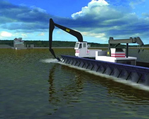
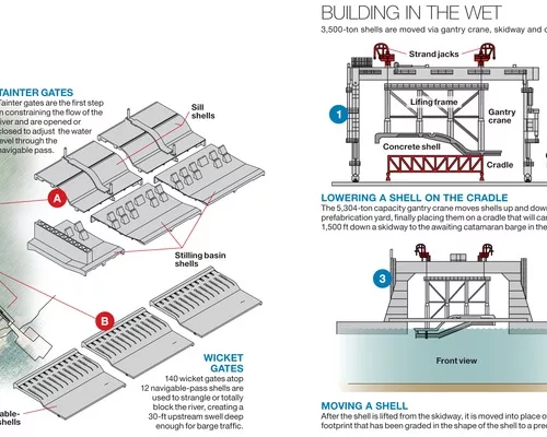
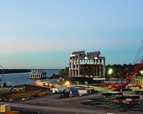
The giant shells are fabricated in a riverbank casting yard, placed on a rail-mounted cradle and brought down a skidway about 1,500 ft into the river so that the awaiting cat-barge can pick them up. A temporary lifting frame attaches to each shell with temporary bolts. Extensions on the bolts run to the top of the frame so that, when the shell is in place, "the world's largest hydraulic torque wrench" turns the bolts from 60 ft above their threading, says Bennett. The bolts are extracted and re-used.
"The frame and the shell together weigh almost 5,000 tons," says Bennett. "We're picking weights that have never been [picked] before."
Once the cat-barge is over the cradle, 10 strand jacks lift the shell and frame. The cat-barge is moved by two tugboats to the setting point, using real-time GPS that, for precision, requires signals from a minimum of five satellites. The cat-barge is secured with an eight-point mooring system that holds it within a 3.0-in. tolerance of its final position. Holding the shell, eight snub points on the platform are used to get the shell within an inch of tolerance as it hangs like a pendulum from the strand jacks.
It only takes two people to operate the strand jacks, says Bob Stelzner, lift master and equipment engineer for URS, but "lowering the shell takes a whole village" to monitor the dynamic process. As the shell begins to slip under the water, the center of gravity shifts and both the loads on the jacks and the reaction forces into the barge change. "We're continually stopping and adjusting on the way down until full submersion," says Stelzner. "Then it's a pretty constant drop until load transfer begins."
Construction Rocket Science
One difficulty is lowering the shell precisely without cracking it; another is knowing exactly where the shell is, from 70 ft above, in the blind.
Clay Jackson, URS construction engineer, and Chris Thompson, URS senior construction engineer, figured out how to do it. Their technology feeds to a screen in the lift room that presents several displays. For example, one area shows a 3D model of the shell and its components, and another shows four bull's-eye targets, registering 15,000 readings per second, that represent the corners of the shell. Data are gathered by two Trimble Robotic Total Stations that reference surveying prisms on the four corners of the platform. Another display shows the elevation of each strand-jack connection point. The shell is kept level by maintaining strand uniformity. With a 0.001º resolution, a dual-axis inclinometer translates shell angles into planer relationships between lifting points. Operators can quickly tell if the 125-ft x 116-ft shell is within the planer tolerance of ±0.5 in. Coordinates from the total stations are displayed to align the shell correctly.
Atop 10 to 12 landing piles, the shell rests on flat jacks used for final adjustments. When the correct placement is achieved, jack positions are frozen by pumping them full of grout, displacing the hydraulic fluid. As the grout sets, it turns the jacks into hard shims. Then the lifting rig is released and the full load transferred to the foundation piles.
Each shell must align with the previous one. The cavity below the shell is then filled with tremie concrete in four lifts. The concrete locks the shell to the foundation, making one homogeneous structure. The shells have 5-in.-dia bleed holes to allow concrete to displace the water inside.
Knowing exactly how far the tremie concrete had risen inside the shells posed another test. URS landed on a "bubbler system" in which pulses of air are pushed through 500 nearly 0.13-in.-dia tubes under the belly of each shell. The pressure encountered at the open ends of the tubes indicates if the tubes are surrounded by water or concrete and what level the concrete has reached. That concrete level is displayed in a 3D model monitored from atop the lifting frame.


