Water Pipeline Designed to Surf Seismic Waves


"In all the projects I've built—and I've built a lot of things—I've never seen any project that's had this level of tolerances required for so many different things," says Pelletier, a 40-year industry veteran.
Large-Scale Components
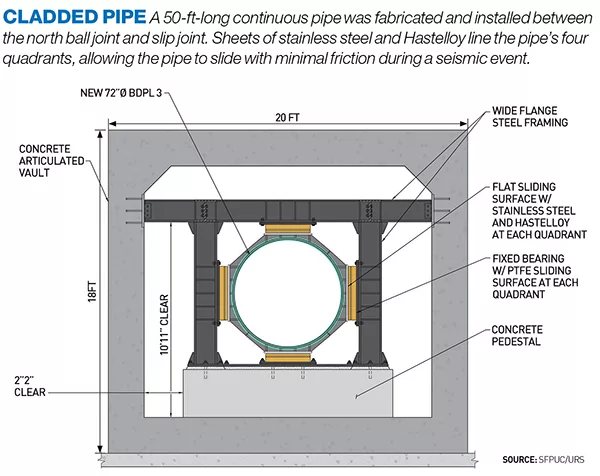
Water from Hetch Hetchy Reservoir, located 167 miles east of San Francisco, makes its way to the 78-in.-dia pipeline No. 3 and 96-in.-dia pipeline No. 4, flowing from north to south at the jobsite. As pipeline No. 3 approaches the new, 305-ft-long vault, a flange reduces the diameter to 72 in., and, at the other end, another flange returns the line to its normal diameter past the seismic zone. The slight step down in pipe diameter was required by challenges in manufacturing the specialized components, says Bryan Dessaure, project manager for SFPUC.
On the north end of the concrete vault, water in the pipe first encounters a unique 25.5-ft-long, 12.5-ft-high slip joint, designed to handle an earthquake's compression forces. Compression is usually the culprit when pipes fail at fault crossings, Czarnecki says. "When the pipe compresses, you get this local bulging or buckling, and you get very high strains around the bulge, to the extent that it can cause a pipe to rupture," he notes.
URS wrote the technical specifications for the slip joint, calling for it to activate or compress during an earthquake at between 50 kips and 100 kips of applied force. However, it fell to Jack Miller, executive vice president of Houston-based Stress Engineering Services, to custom design and fabricate the 77-ton device. Challenges immediately arose.
After calculating the pressure inload resulting from the pipeline's normal operating pressure, Miller quickly discovered there would be over 500 kips of load trying to push apart the two pieces of pipe making up the slip joint, the exact opposite of what needs to happen during an earthquake. "Their specification called for a load to slide the slip joint together that was on the order of 10% of the load that actually exists in the pipe every day under normal operating pressure," Miller says. "When I read that, I thought, 'There's only one way I know how to do that.' "
Following concepts borrowed from the oil industry, Miller used pressure balancing to neutralize the pipe separating load by applying an equivalent pressure in the opposite direction. Eight 28-in.-dia, 12-ft-long pressure-balancing cylinders—each weighing 5,300 lb and holding up to 205 cu ft of water—surround the slip joint. Ports connect the cylinders to the inside of the slip joint so that they experience the same water pressure as the pipeline. Pistons and rods within the cylinders attach to the end of the slip joint and pull in opposition to the water pressure's force. "Even though it's free to slide, it doesn't because everything is in equilibrium," Miller says.
Pressure-balancing was critical to allow the slip joint to compress easily to absorb seismic motion. "Whenever you have this sliding or seismic event where the pipe needs to collapse, then the slip joint will allow that to happen without any negative effects," Miller adds.
The two massive barrels composing the slip joint were 100% machined from rolled and welded steel plate by Metalex, Cincinnati. Because the inside of the nearly 2-in.-thick barrels had to be bored, Metalex was one of the only machinists that had a long enough boring machine for the job, Miller says.


