Chicago Team Struggles To Impose Order on Chaos
 |
| (Photo by Michael Goodman for ENR) |
The flashy silver "lion" with an unruly mane enthroned in Chicago’s $475-million Millennium Park is the city’s first Frank O. Gehry structure. And the "newbies" chugging along the yellow brick road toward completion of the avant-garde music amphitheater by architecture’s Wizard of Oz are exhausted by the $45-million job’s sundry twists and hairpin turns.
A learning curve is just about the only thing missing from the long and winding road to complete the king of all beasts in the 24.5-acre park. "This experience is collectively grinding on all of us newbies," says James Conrath, project manager in the local office of URS, the owner’s representative. "X, Y, Z is not as easy as A,B,C," he adds, referring to the lion mane’s coordinate geometry.
Even Gehry veterans find it difficult to impose order on his deliberate chaos. "With Frank Gehry, every project throws a whole new set of challenges," says Hugh Dobbie, president of Dowco Consultants Ltd., Burnaby, British Columbia. The amphitheater follows Dowco’s previous stint as steel detailer on Gehry’s Los Angeles concert hall. "After you’ve been burned, you have trouble bidding against" the uninitiated naive enough to bid low, he says.
 |
| (Photo courtesy of Walsh Construction Company) |
The pavilion has a wood-paneled stage with a 90-ft-wide and 50-ft-tall opening. Sliding glass proscenium doors, mechanically operated, will allow year-round use. The stage roof and "mane" structures are expressed, like a permanent backdrop. Under a trellis, there will be 4,000 self-rising seats and space for another 6,000 people on the lawn. ![]() Click here to view diagram
Click here to view diagram
The 625 x 325-ft trellis, 60 ft at its highest point, defines an outdoor "room" of sorts, but its primary purpose is to hang loudspeakers for a computer-controlled sound system. The system consists of speaker clusters at the stage and loudspeakers distributed over the audience area. A pedestrian bridge approach alongside the lawn will double as a sound berm, containing the music and keeping away ambient noise. Acoustically, "we were able to create a room effect," says Craig Webb, project designer for Gehry Partners, Los Angeles, by delaying the sound by milliseconds as it is distributed. "It’s like a surround sound system in a movie theater."
|
To stay the course in Chicago, the contractor stumbled, at first, along the road of computer-enhanced construction. Vets and newbies alike say three-dimensional solid-object modeling, "net" meetings via the Worldwide Web, high-tech surveying methods and computer-aided fabrication made the project feasible. "Without the 3-D models, we would still be in shop drawings," says Patrick R. Buck of local Walsh Construction, the general contractor for the music pavilion and other jobs in the park near Lake Michigan. Buck is project manager for the wavy tresses, their support steel and for the silver trellis over the seating area.
The project’s tough logistics demanded lots of coordination, especially for the lion’s mane. There, even the 352 x 625-ft trellis pierces the tresses, like a giant hairpin.
![]() Click here to view diagram
Click here to view diagram
The 3-D models were part of the team’s salvation and part of the problem. "Getting everyone educated on 3-D software was one of the major challenges," says Buck, especially because Walsh was traffic cop for five different models used by players scattered all over America.
Net meetings, which allowed remote players to view, rotate and discuss the model in real time, were a big help. There were 80 meetings from February to October 2002 on the tress support elements alone. The meetings kept the shop drawing phase from bogging down, says Buck, who figures he saved Walsh’s $35,000 computer system investment in travel costs alone.
"It was almost like approving shop drawings before they came," says John Zils, associate partner in the local office of project structural engineer Skidmore, Owings & Merrill.
The meetings slashed the number of requests for information. For pavilion steel, including the trellis, there are 125 RFIs. Without meetings, Conrath estimates there would have been some10,000 RFIs on tress support elements alone.
 |
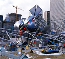
| FIELD FIX Compass-arm positions adjusted. (Photo courtesy of Walsh Construction Company) |
But even 3-D models and net meetings didn’t prevent a significant stumble last summer, when the team discovered, after erection, that many of the "compass arms" shop-welded to the elements to receive the tress panels were not in the right place.
"This whole issue of [tight] tolerance on multidimensional buildings needs to be looked at differently," says L. William Zahner, CEO of A. Zahner Co., Kansas City, Mo., and a Gehry vet who designed, fabricated and installed the panels. Often, "what we attach to floats all over the place," says Zahner.
In anticipation, Zahner makes the surface "as adjustable as we can within the space of the wall panel," he says. Typically, that means doubling the tolerance allowed for panel supports.
To assess the problem and devise the fix, Walsh turned to technology. Using a high-tech scanner, the team produced an as-built model of the hard surfaces of the elements, to compare them to the theoretical model.
Of 2,064 arms, 489 in the center and east elements had to be replaced or adjusted, says Dowco.
The team still has not sorted it all out. Walsh says Dowco’s number is wrong. Steel fabricator Lejeune Steel Co., Minneapolis, declines comment.
Everyone is vague about how much the snafu slowed the project, which is now set for substantial completion at April’s end instead of mid-March. But Zahner, which just finished installing the 700 panels, says he didn’t expect to be installing panels in winter.
"Our initial projections were that [the pavilion] would be done sooner, but we didn’t try to schedule ‘genius’ to the midnight hour," Conrath says.
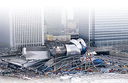
The opening celebration of Millennium Park is now set for July 24, a date that also has moved. Chicago’s grand civic gesture began with a 1997 master plan by SOM for an expansion of the northwest corner of Grant Park, atop a three-level, 16-acre platform over existing rail tracks, a bus lane and a future commuter station. It was supposed to be done in 2001. ![]() Click here to view diagram
Click here to view diagram
 |
| CIVIC GRANDEUR Sixteen-acre park turned into a 24.5-acre park. (Photo by Michael Goodman for ENR) |
Plans changed when the Pritzker family agreed to give $15 million toward the music venue if the city switched gears and made the park an architectural statement, with Gehry as the exclamation point. Mayor Richard M. Daley (D), the park’s big booster, agreed.
The park was then expanded to 24.5 acres and the grand opening pushed to 2002 to accommodate the Gehry pavilion, whose tresses and trellis are paid for with $18.5 million from donors.
The platform levels, already under construction when Gehry arrived in 1999, have stayed true to the master plan.
But the park level plan has been morphing. There are now 10 projects underwritten by $205 million from donors. The changes and delays in fund-raising and letting contracts pushed the opening to this summer.
The city’s $270 million is mostly for the pavilion’s $25-million base building, the $204-million Millennium Park garage and park infrastructure. The 2,181-space garage is the major funding mechanism to pay off $170 million in city bonds.
A $2.7-million ice rink opened in December 2001. A $4.5-million replacement of a landmark peristyle was completed in October 2002. A $52-million, 1,500-seat underground music and dance theater, which shares back-of-the-house space with the pavilion, was finished in November. A $12.1-million pedestrian bridge, Gehry’s first span, is to open in July, along with a $10.2-million ornamental garden. A $10-million sculpture resembling a giant kidney bean should be completed by August and a $12.5-million reflecting-pool sculpture consisting of two rectilinear towers with facing projection screens by October. Landscaping is to be done by July.
According to projections, the cultural and recreational park will bring in $250 million additional tourist dollars each year. The city’s small investment in cutting-edge architecture is already paying off, says Edward K. Uhlir, assistant to the mayor and Millennium Park project director. Area real estate prices are soaring and work is under way or complete on several hotels and residential buildings nearby.
URS arrived in June 2000, when the Public Building Commission took over administering the project from Chicago’s Dept. of Transportation. The garage, delayed by design problems, was opened in phases; the north part in February 2001 and the south that December.
For construction, the city broke the park projects into many contracts. The approach "made coordination more difficult," says Conrath, but it was the only way to go because the park elements came into being at different times.
URS is one of three owner’s reps that report to Uhlir. City contracts are lump sum, low bid. Donor-funded contracts are typically negotiated.
Gehry expedited the music pavilion design, finishing in November 1999, so that adjustments could be more easily made in the platform structure below.
For the structural engineer, the biggest challenge was devising a consistent geometry to take the "free out of free form," says Zils. For the 3-D tress elements, all made of straight members, SOM superimposed a grid of virtual horizontal planes every 10 ft and virtual vertical planes every 9 ft, 8 in., and then mimicked the tress forms. The vertical planes conform to the garage’s 29-ft structural module.
 |
| SLOTS Some 700 doubly curved panels are required to remain true to the designed surface. (Graphics courtesy of A. Zahner Co.) |
The 12 elements, made of wide-flange ribs, horizontal tubes, diagonal braces and pipe supports, extend across an area 320 ft wide and up to 142 ft. The five center elements bear on tips of 12 trusses that cantilever 70 to 100 ft off the proscenium truss girder, and are stiffened by braces. SOM lined up element ribs with cantilevers. Three other elements are supported by braces and four sit on the platform’s raft slab. ![]() Click here to view diagram
Click here to view diagram
To simplify the analysis model, SOM introduced a theoretical shell element that requires very little stiffness to distribute the load. The engineer also modeled the base building frame and elements as one. SOM had to interface with and support the design of the panels. For example, panels act like wind catchers. To ensure they wouldn’t vibrate, SOM did a dynamic analysis. Though their curvature stressed some, it made the panels very stiff and unlikely to vibrate, says SOM. ![]() Click here to view diagram
Click here to view diagram
 |
| PIERCING Like hairpins, trellis runs through curved panels "coiffing" the proscenium, complicating steel work. (Photo by Michael Goodman for ENR) |
The steel pipe trellis is a bilaterally symmetrical, two-way intersecting arch form–a shell structure. The trellis consists of 24 flat arches, two each the same, made of 12 to 18-in.-dia pipes. The arches spring from parallel lines of twelve 6-ft-dia concrete pylons, 15 ft tall and 60 ft apart. One flatter and one steeper arch spring from each pylon and land on different pylons along the opposite line.
SOM imposed a two-way diagonal grid system on the architect’s random arch configuration. Intersecting arches meet on the same theoretical surface, says the engineer, but at different angles.
For economy and constructibility, SOM worked with Gehry to reduce the number of radii per arch to four. Radii change at the welded nodes. For economy in fabrication, SOM designed the arches to curve in one direction only.
The pylons, which take the arches’ thrust, had to be stiff to control deflections and the trellis shape. A small deflection at a support would be magnified at the center. Gehry didn’t want a simpler tension ring at the ends of the trellis.
Temperature-related movement of the trellis’s substructure, through two expansion joints, had to be part of the 3-D finite element analysis.
 |
| FALSEWORK Towers are under cantilevers until elements are up. (Photo courtesy of Walsh Construction Company) |
To erect the trusses, the steel erector used twelve 78-ft-tall shoring towers, one under each tip of each cantilever. The erector designed and positioned the falsework to allow erection of catwalks and primary steel for the five center elements.
Towers had to remain until the trusses and center elements were complete and surveyed. Then, towers were relieved of their loads simultaneously. SOM’s predicted deflection for dead load was 3 3 /4 in. The tip deflection of the longest cantilever was some 3 in., says Dave Budzius, project manager for steel erector Danny’s Construction Co. Inc., Gary, Ind.
The engineer predicted additional deflection of 3 /4 in. due to superimposed dead load and some 2 in. of live load deflection. DCCI measured a total of approximately 6 in. of deflection.
The metal elements weigh from 15 to 96 tons. Some of the larger, heavier elements had to be installed 142 ft above grade. The weight combined with their configurations, plan positions and elevations, required the use of large cranes, says DCCI, which erected the elements in six months starting last Feb. 18. Erection detailing was completed on Sept. 12.
In preparation for the lifts, large sections of the elements were assembled at grade level, rigged and lifted into position with one crane while the second crane erected the braces and in-fill steel. Erection moved west to east. Placing the at-grade elements first allowed the first elevated element to be erected over its top. Once the west elements were erected, the cranes tracked east as the crane grillage leap-frogged with the cranes to the east.
Center elements were erected next. When the eastern-most center element was erected and detailed, crews removed truss falsework.
The majority of the trellis system was erected from June to the end of September 2003. Trellis erection involved approximately 165 full-penetration field welds. The coordinated detailing and erection scheme provided 120 pipe pieces, varying from 50 to 105 ft long, with average 80-ft lengths.
Shoring towers supported the trellis at 48 node points. A braced top beam supported devices that suspended the trellis near the node point. The suspension slings were positioned slightly offset of the node points to allow for accurate surveying of the punched-marked node points. By suspending the nodes in lieu of placing shims or jacks, DCCI was able to quickly and accurately adjust the node elevations, says Budzius.
The design documents allowed the trellis to be erected either from north or south. The team decided to erect from both directions at once, starting from the south, where there were minimal logistics issues and a need to complete sooner to make way for construction of a garden.
Due to the crush at the north end, the team erected the two north diagonal grids in conjunction with the tress elements. This would allow field welds to be done sooner, says Budzius.
Two-directional erection creates potential for a misfit at the juncture. Thanks to the suspension tops and diagonal drop-down field splices, the fill-in pieces were successfully erected and positioned, says Budzius.
North trellis piping comes within inches of tress elements, braces and the catwalk. To avoid a traffic jam, DCCI set the center trellis intersection node in advance. It was delivered in pieces and assembled on the slab. After its geometry was verified, it was fully welded as one unit. In conjunction with the element erection, DCCI used both cranes to erect the 76-ft-long node and suspend it from the cantilevers. After that, DCCI erected the center elements.
The east and west elements are also proximal to the trellis. By coordinating the north erection scheme’s field splices, DCCI was able to position shoring towers so they would not interfere with elements, says Budzius. With the use of a shoring bent, DCCI erected the node of the trellis directly above the most easterly element, without imposing on it.
The nearly 700 panels–no two alike–followed the elements. The panels, ranging from 4 to 8 ft in width and 6 to 24 ft in length, are made from high-strength aluminum plates, or fins, cut to the profile defined by Gehry’s model. Each fin has a unique position within its frame, determined by a proprietary algorithm, which analyzes the solid model surface of Gehry’s design. "We have applied for three patents on the software system," says Zahner.
The result is a series of shapes determined by the computer that are cut and assembled into frames on the shop floor, using computer numerically controlled equipment.
The system allows Zahner to make the surface several months in advance of steel erection. It works well if issues don’t develop with the steel, he says. On site, crews adjust panel-to-panel alignments to create a smooth and continuous surface. Crews then cover the front surface with a total of 5,200 interlocking, stainless-steel sheets.
 |
| (Photo courtesy of A. Zahner Co.) |
Panels are hooked into holes in compass arms via a two-part assembly that allowed the panel to roll into position. A fork on the lower end of the panel going in "grabbed" an anchor with a milled-out steel ring with a Teflon band, bolted to the top of a previously installed panel below.
![]() Click here to view diagram
Click here to view diagram
Crew started installing panels last May. Substantial completion of the system is set for the end of the month. "The center was the hardest because of odd shapes and installing panels overhead," says Zahner.
As they near the end of the road, some of the players clearly can’t wait to get back to Kansas. One even jokes that his next job is going to be a Wal-Mart. But along with grousing is an air of accomplishment. "In legacy projects, there is a certain sense of pride," says Wayne Anderson, Walsh’s senior project manager. "Nobody can take that away."