Movie of Job that Defies Description Is Worth More Than A Million Words
 |
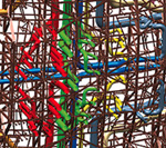
| MODEL AUDITORIUM 4D visualization tool sequenced steel erection. (Photo courtesy of Warren Aerial Photography Inc.) |
It's a classical music palace named for the king of cartoons in the film capital of the world. It has a 15-year history that reads like a Hollywood drama–with budget busts, fits, stops, restarts, cast changes and rewrites. But that's not why the contractor for the 293,000-sq-ft Walt Disney Concert Hall donned a producer's hat and commissioned an animated "documentary" about the job. It was more because, if the star of the show is a description-defying building designed true-to-formless by Frank Gehry, then a moving picture is worth a million words.
The exuberant architecture would have been daunting enough. But the new $274-million home for the Los Angeles Philharmonic, set to open in the fall of 2003, has exacting seismic and acoustical demands. "I don't think there is a single component that is not challenging," says Jim Yowan, project director for the Los Angeles office of M.A. Mortenson, the general contractor-construction manager for the roughly $200-million job.
Something had to be done to engage the subcontractors, who were overwhelmed by the job. Convinced that previewing is believing, Mortenson decided to tiptoe into the fourth dimension of computer modeling and marry the building's curvilinear, leaning and swooping geometry to the planned schedule. The output is an animated 4D CAD visualization tool that plays out the construction sequence. "Instead of printing out large flow diagrams" to communicate how to construct, "we were able to play a movie," says Derek Cunz, Mortenson's project manager.
The effort has pushed the project into the vanguard of computer-aided construction. "The scale of the application is, to my knowledge, unprecedented in the world of buildings," says Martin Fischer, director of Stanford University's Center for Integrated Facility Engineering, Stanford, Calif.
 |
Based on Fischer's suggestion, Mortenson hired Stanford doctoral student John Haymaker to create a 4D model of the most complex components using Walt Disney Imagineering software licensed by Mortenson. It took four months to model the skin, a curvilinear structure and the auditorium interior and ceiling.
 |
| BIG SQUEEZE 3D CAD model shows (above) ductwork snaked around steel in hall's upper reaches (above left). (Photo by Michael Goodman for ENR, Illustration courtesy of Mortenson) |
Mortenson used the model to comprehend, confirm, communicate, coordinate and troubleshoot. The tool helped find logic busts in the schedule while there was still time to adjust. It verified constructibility and checked work flow, access and hoisting. And it helped educate Mortenson's team. But primarily, it was shown at monthly coordination meetings to preview the next 90 days of work. After the model's mid-2000 "premiere," the subs uncharacteristically lingered for 90 minutes, chatting about the job. Mortenson's general superintendent, Greg Knutson, was "blown away" by that, recalls Fischer, who attended the first showing.
Harry Adams, project manager for Cerritos, Calif-based electrical sub SASCO, says the model is "very helpful, especially coordinating with other trades." It "lets me know where I need to be," adds Gino Capra, general foreman for Martin Brothers/Marcowall Inc., the Gardena, Calif.-based plaster-drywall contractor.
Not everyone is as enthusiastic. Dennis Demmert, project superintendent for Glendale, Calif.-based mechanical sub ACCO, says the 6,000 hours budgeted for detailing ballooned to more than 20,000, and there were hundreds of requests for information (RFIs). The model also was heavy on structure but didn't show "how physically to get ductwork" sections through the forest of steel during installation, he says.
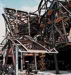 |
| JUMBLE Dense frame handles strange shapes, seismic loadings. (Photo courtesy of Warren Aerial Photography Inc.) |
The model isn't perfect, but it is apparently on target. "We are following the schedule to the ‘T,'" says Knutson, and the job is on course for an April 2003 completion. Then, Mortenson will turn the facility over for six months of commissioning.
The 4D model may have been helpful but the 3D CAD model, developed to avoid drawing thousands of details and to relate one installed building system to another, is considered absolutely indispensable. "The contractor has more information to assist in building this project than probably on any other in the history of architecture," says Terry Bell, Gehry Partners' project manager.
Capra agrees: "Everything is driven by CATIA. It allows us to be creative."
 |
| SHORED BY 4D Erector got to preview south wall erection. (Photo courtesy of Herrick) |
Frank Gehry has said many times that 3D CAD is the key to his brave new paperless world of building. In Gehry's world of sculptural forms, the architect reigns over the rest of the construction team by controlling the CAD model. Toward this end in 1990, he hired partner Jim Glymph to bring 3D CAD into Gehry's Santa Monica, Calif., studio.
The concert hall was the first guinea pig. But the architect was way ahead of his time. While his shop painstakingly digitized surfaces, nearly everyone else down the line functioned the old way. "It was ill-organized," says one consultant involved in the early exercise.
That was then. In 1994, the project stalled. By the time it restarted in 1997, computers had infiltrated construction. Gehry's jobs are still not paperless. But most, like the reborn concert hall, are hybrids, with construction documents that contain drawings and a CAD file.
Toward a paperless end, Glymph envisions a team-shared project platform that centralizes all data, allowing instant feedback for fabrication, material quantities and more. The system would recognize objects and their attributes, and be able to work across the Internet. The firm is currently working with IBM and Dassault Systemes, developer of CATIA, the 3D program Gehry uses, to evaluate an "intelligent" package specifically for buildings.
The concert hall complex, a full-block addition to the Music Center of Los Angeles County, consists of eight elements above grade and a 70- x 58-ft theater below, cut into a parking garage completed in 1995. On city land, the facility will be county owned and operated.
The concert hall is formed by a three-dimensional braced frame in structural steel that bears on the structural concrete garage. The frame contains nearly 11,000 tons of steel and more than 11,000 pieces, almost all different. The connections join as many as 10, usually dissimilar members. "It's very dense," says John A. Martin Jr., president of the job's local structural engineer, John A. Martin & Associates Inc.
Martin selected a braced frame as the most efficient and economical, under the circumstances. The behavior of a braced frame is more predictable in a quake than a more-limber moment frame, he says. But a braced frame delivers much higher instantaneous loads back to the ground, in this case through the garage. "We have what appears to be substantial bracing because we wanted to distribute the forces as much as possible" over the garage's top slab, Martin says.
Even so, the engineer had to reinforce portions of the slab and some garage columns and their foundations.
 |
| FLARED North wall, with cantilever, was trickiest to erect. (Photo courtesy of Herrick) |
Though some see the braced frame as a "brute-force solution" that has had a negative impact on the trades that followed the steel, Martin is pleased with it. "It solved our lateral load problems," he says, and fit into the garage structure.
The clunkiness is in part attributed to the project's storied past. In 1988, Gehry won a design competition for the concert hall without having completed any project of this scale. Completion was set for 1996. Dworsky Associates was the local executive architect and CBM Engineers Inc., Houston, structural engineer. The local general contractor was Concert Hall Builders, a three-firm joint venture including Peck/Jones.
By November 1994, with the garage almost finished, the hall's design 90% complete and steel fabrication about to begin, the cost of the fast-tracked job had escalated $50 million, to $260 million. The Walt Disney Concert Hall Committee then pulled the plug on the job. When it was revived in 1997, Gehry had promised to redesign the building with primarily a stainless steel skin, not limestone cladding. And under threat of withdrawal, he had been given his first role as executive architect. "We want to do our own construction documents" and "control our own destiny," says Craig Webb, Gehry Partners' concert hall project designer.
But the building code had since changed as a result of the area's 1994s Northridge earthquake, which rattled confidence in special moment-resisting frames. The nonrepetitive moment frame had become too costly, thanks to a new code stipulation that moment connections had to be laboratory tested. A structural redesign was in order. Gehry, knowing extensive coordination was necessary, wanted a local engineer, says Edward J. Burnell, president of Walt Disney Concert Hall I Inc., the development manager formed for round two.
CBM was given the option of opening an L.A. office or taking responsibility for garage changes and serving as a consultant to Martin on the hall. Neither course was acceptable, says P.V. Banavalkar, who retired from CBM in 1999 and is currently a vice president with Carter Burgess, Houston.
There were other changes. After a two-year preconstruction phase in 1997, Mor-tenson signed its lump-sum, at-risk contract in late 1999 (ENR 12/20/ 99 p. 16). And the job was no longer fast-tracked.
 |
| CONFUSION Except for box columns, it is tough to tell shoring from steel. (Photo courtesy of Herrick) |
The redesign of the hall was done in the first nine months of 2000, concurrent with the retrofit of the garage. This included reinforcing, cutting into the top slab and two post-tensioned slabs below it for the theater and beefing up the slab for crane paths.
Martin considers the amorphous elements the most complicated in the facility. Trying to hit a theoretical point in space, given allowable tolerances, was "very challenging," he says. "The process of thinking in 3D is not just a philosophy but a state of mind."
Framing for the preconcert hall (Element 3), the founders' hall (E-8) and even the conductor's suite (E-6) with ribs in the horizontal plane is reminiscent of the rib-stiffened reinforced shotcrete shells of Gehry's Experience Music Project in Seattle (ENR 2/28/00 p. 76). Pipe sections provide lateral bracing.
The lobby area (E-4) is also curvilinear. It is framed from 8- and 16-in.-square straight tubes that primarily resist lateral loads. Its 2-ft-square built-up box members and up to 30-in.-deep built-up ribs create 3D curved trusses. The north end is framed by sloping 30-in. deep built-up ribs. The atriums (E-2 and 5) bracket the auditorium. They are framed by sloped wide-flange columns in a semicircular shape.
The 238- x152-ft auditorium is a warped box. It has flared walls, up to 130 ft tall, and a flattened-V roofline, doubly pitched 14°. The south wall leans out 17° from the vertical. The other three walls lean 6°. The roof slab, 14 in. of concrete on metal deck, is supported by nine dissimilar trusses that span up to 140 ft east to west. The extra-thick slab is mostly for acoustical isolation. Built-up box columns, typically 2 ft but up to 30 in. square in the plane of the leaning walls, support the trusses.
E-7 forms a platform that transfers loads from other elements to the garage. It has a regular frame, though some columns slope at their bases to line up with the garage grid. At the south end, E-7 rises above grade to house the orchestra's offices.
 |
| ELEMENTAL Steel frame is true to surface geometry of eight elements. (Photo courtesy of Warren Aerial Photography Inc.) |
To fabricate steel for the project, the steel contractor used two of its own facilities and six others, in an effort to keep fabrication ahead of field work.
Nearly 80% of detailing was done using a 3D model-based platform called Xsteel, recommended by Gehry prior to contract award, says Roger E. Ferch, vice president of steel contractor Herrick Corp., Pleasanton, Calif. The platform offers a more direct link to CATIA than a 2D system and permits the transfer of data in both directions. For example, CATIA starts with a steel wire frame. Xsteel then provides it with member shapes and dimensions, which was helpful to Mortenson and the design team.
The warped box was the most difficult element to erect, says Ferch. Within that, the trickiest part was a 40-ft cantilever on the upper half of the north wall. Otherwise, steel erection was relatively simple, though the EMP-like elements did require internal table-like shoring against which the ribs leaned temporarily, he says.
Work started at the south wall by erecting an engineered shoring tower, which bore on E-7 framing, to cradle the leaning columns until appropriate connections were made. The 121-ft-tall tower consisted of two A-frames at the base, 72 ft apart, connected by horizontal members. Continuing up from each "A" was a vertical member. Three flat, horizontal trusses, each 133 ft long, spanned between vertical members like ladder rungs, and cantilevered beyond them. The columns went up in three pieces, the top of each set against a rung.
Shoring for the 120-ft-tall north wall consisted of 100-ft-tall supports at the corners with two mid-wall supports that broke the wall into thirds. A triangular support, some 50 ft tall, supported the base of the cantilever's column, which like the wall leans out 6°.
 |
| PRODUCERS Mortenson's Knutson (l.), Yowan, Greg Funk. (Photo by Michael Goodman for ENR) |
East and west walls were simpler. Some columns gained support from E-2 and 5, which went up concurrently with the box. Another was guyed to a previously erected structure.
The first steel was erected in July 2000. Using a 300-ton crawler crane, Herrick set a portion of E-7 above the theater, for south wall shoring. The crane then moved north, inside the box. Six months into the work, a 170-ton mobile crane started E-6 and the balance of E-7. E-3, 8 and 4 followed. Later, a 50-ton hydraulic crane erected interior steel. Primary structural steel cost $2,500 to $3,000 per ton.
Mortenson insisted on 100% fall protection above 6 ft on the entire project. But because of the shapes, conventional fall protection systems, designed to hook onto flanges, wouldn't work on a majority of members. Mortenson and Herrick came up with a system that involved detailing fall protection cable attachments on the shop drawings so field personnel could install cables on the beams. Two people fell during the project and were restrained by the system, says Mortenson's Knutson. There have been no deaths or major injuries, he reports.
Mortenson and Herrick also devised a scheme to check positioning of the steel. In the shop drawing phase, target positions were identified on selected pieces. In the shop, target locations were center-punched on the member and in the field, crews placed a reflective target over the punchmark. That allowed the surveyor, using a high-tech transit with its own database containing X-Y-Z coordinates for each piece, to know when the piece was in its correct position.
 |
| SWEEPING Steel frame considered most complex in U.S. (Photo by Michael Goodman for ENR) |
Steel was substantially erected by late last year, with a "miniscule amount out of tolerance," says Mortenson's Yowan. Final connections of major members involved field welding, finished earlier this year. The job was done on time, says Ferch, but with over 2,000 RFIs.
No one will comment on changes, extras or claims on the steel or any part of the project, saying the information is confidential.
he skin followed the steel. The surface will eventually contain 160,000 sq ft of panels and 40,000 sq ft of glazing. Of 6,100 panels, only 2,100 are the same.
The panel system was designed and detailed using CATIA and then fabricated using computer numerically controlled equipment driven by the CATIA model. It is the most complete use of CATIA on the job, says the architect.
We decided to spend a lot of energy on design so everything is in the model," adds Marzio Perin, engineering manager in the Los Angeles office of Permasteelisa Cladding Technologies. That saved a lot of time in the end, he says.
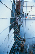 |
| THIN SKIN Curtain wall supplier-installer used 3D CAD the most. (Photo by Michael Goodman for ENR) |
The panels are installed on a secondary frame anchored to the primary frame. Layout of anchors is controlled by a field instrument, called a total station, that provides X-Y-Z coordinates for a point interfaced with custom software that sets the anchor according to information received from CATIA. Workers then bolt secondary frame members-metal studs or aluminum channels containing CNC shop-drilled bolt holes-to the anchors. Crews adjust the studs according to the layout in the CATIA model. Next, workers bolt girts, which support the panels along their lower edge, to the secondary frame. Girts also have CNC shop-drilled bolt holes. Girts are adjusted left and right, again following the CATIA model. Position is checked by the total station. Finally, crews install panels.
The skin is only 50% complete, yet the building is already a landmark. New York has the Statue of Liberty, Rome has the Coliseum and Paris has the Eiffel Tower, says Burnell, hoping that the Walt Disney Concert Hall will replace the "HOLLYWOOD" sign as L.A.'s icon.