Transit Projects
Sky Train Extension to Ease Traffic Around Phoenix Airport
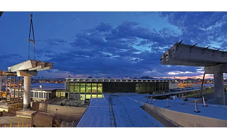
Tub girders that support the PHX Sky Train system extend over an existing terminal scheduled for demolition.
PHOTO COURTESY OF HENSEL PHELPS CONSTRUCTION CO.
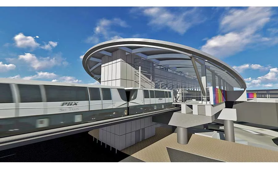
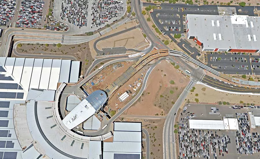
Upon completion, the Sky Train extension will terminate at a consolidated rental car facility featuring a new station with a two-directional elliptical roof.
IMAGE COURTESY CITY OF PHOENIX AVIATION DEPT.
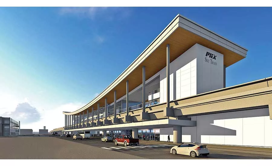
Before reaching the rental car facility, another new station will deposit riders at a ground transportation center.
IMAGE COURTESY GANNETT FLEMING INC.
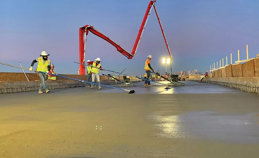
Atop the superstructure, crews place an 8-in.-thick concrete deck to support Sky Train components.
PHOTO COURTESY HENSEL PHELPS CONSTRUCTION CO.
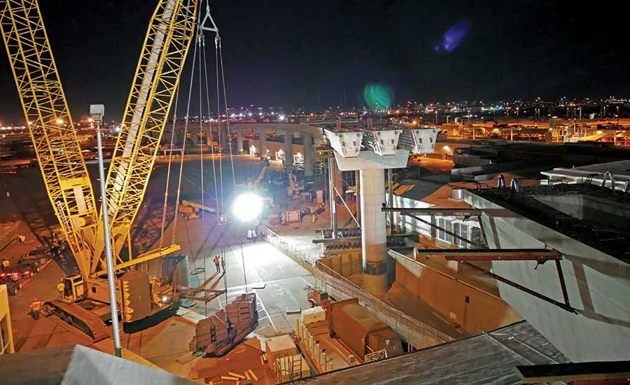
A Liebherr LR 1300 derrick boom crane with a 300-ton capacity was among the equipment crews used to place girders.
PHOTO COURTESY HENSEL PHELPS CONSTRUCTION CO.
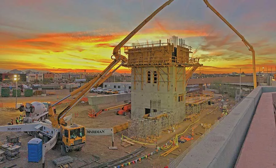
Crews perform early concrete placement at the rental car facility station.
PHOTO COURTESY HENSEL PHELPS CONSTRUCTION CO.
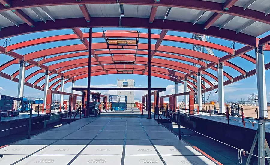
The roof at the rental car facility station is supported by beams that were shaped using extreme heat to achieve an arched configuration.
PHOTO COURTESY HENSEL PHELPS CONSTRUCTION CO.
The Sky Train extension, which will terminate at the rental car station, is expected to serve millions of passengers a year.
PHOTO COURTESY HENSEL PHELPS CONSTRUCTION CO.
The 2.5-mile extension of an automated sky train system, currently under construction at Phoenix Sky Harbor International Airport, will go a long way toward easing traffic tie-ups by eliminating the buses that shuttle between a ground transportation center and the airport’s rental car facility.
The electrically propelled PHX Sky Train also will reduce emissions generated by vehicles, thereby reducing the airport’s carbon footprint, says Kyle Kotchou, deputy aviation director of design and construction with the city of Phoenix Aviation Dept.
The $740-million project—which includes 24 electrically propelled vehicles, an underlying dual-lane guideway, the supporting superstructure and a pair of stations—marks the third stage of a 16-year effort to connect major airport facilities via a system supplied by Montreal-based Bombardier. Previous stages, designated 1 and 1A, consisted of a 2.4-mile line that connects a regional light rail system to airport terminals. The initial fleet of 18 trains travel at an average speed of 23 mph.
The current project, which broke ground in 2018, picks up where previous stages left off—at Terminal 3, the airport’s westernmost terminal. From there, Bombardier INNOVIA APM 200 vehicles, identical to those deployed in previous stages, will shuttle 79,000 passengers a day to and from the rental car facility.
As with the original line, many project team members also are picking up where they left off, returning to participate in Stage 2. “Experience and a solid knowledge base of the system figured significantly in our selection of a construction manager, civil engineer and other players,” says Don Weiler, project manager of installation and start-up with Bombardier.
The city hired the firm to oversee design, construction and integration of components for the guideway trains, from switches and signals to electrical distribution and communications systems. The Phoenix offices of The Weitz Co., as primary subcontractor to Bombardier, and civil and structural engineer Kimley-Horn are reunited; both firms worked on Stages 1 and 1A.
The project’s fixed facilities work—including the guideway’s reinforced concrete superstructure, with attendant foundations, columns, pier caps, tub girders and guideway deck—reconnects Phoenix-based designer-of-record Gannett Fleming Inc. and construction manager Hensel Phelps Construction Co. The team also is building the two new stations.
Lessons Learned
Both teams are paying close attention to the more than 200 lessons learned from previous stages, says Alex Bertolini, operations manager with Hensel Phelps. “Among other modifications, we engaged our power subcontractor earlier, during initial planning,” he says. “Our team also coordinated earlier with Bombardier and Weitz in schedule development.”
Careful coordination between the fixed-facilities and guideway teams is particularly critical, Bertolini says. Terminal platforms and train cars need to have only a small gap between them and provide a smooth, seamless experience for vehicles such as wheelchairs.
“You can only have so many crew members at a single point at one time before creating a bottleneck.”
– Andrew Klem, Project Manager, The Weitz Co.
After conducting various studies, the fixed-facilities team charted a mostly linear westward route between Terminal 3 and the ground transportation center. From there, trains will travel west and south before ending at the rental car facility. To some degree, the route was self-defining, given the need to circumvent existing facilities, airfields and the like, says Mark Pilwallis, principal with Gannett Fleming.
Nearly 70% of the route is above grade, reaching heights up to 60 ft, and then closer to 30 ft at points where the trains enter and depart stations. The remaining 30% of the route runs at grade, as train cars pass through an existing Interstate 10 underpass as well as a newly created underpass below planned taxiways.
The existing underpass accommodated two lanes of eastbound and two lanes of westbound vehicular traffic, but the roadway was largely underused. Crews simply realigned and compressed the road for the guideway. Building it above the interstate highway wasn’t feasible because that would have interfered with existing air space, Pilwallis says.
The newly created underpass is 71 ft wide and 600 ft long from exit to entry points, comprised mostly of reinforced-concrete structural components. Slightly less than half the width will be used for future vehicular traffic in support of airport operations, with the remaining 34 ft designated for the train’s guideway.
Both halves are supported by a 3-in.-thick, poured-in-place abutment on one side and a poured-in-place pier—or continuous wall—on the other, says Pilwallis. A total of 110 precast, prestressed box girders, 55 to support each taxiway, are located at 4 ft intervals, spanning the abutment and pier caps. The foundation consists of 4,000 spread footings. At grade, planes will taxi across a 6-in.-thick reinforced-concrete slab that tops the underpass.
Nonlinear Construction
Construction of the train system is not proceeding in one direction, but from both ends and points in between, Bertolini says.
The guideway measures 15 ft wide for a single lane, 30 ft for a dual lane and 50 ft at the switch area, so “we’re dealing with a very narrow space,” says Andrew Klem, project manager with Weitz. “You can only have so many crew members at a single point at one time before creating a bottleneck.”
Placing crews at multiple locations not only spreads out the workforce but also keeps headcount at a steady level. “Rather than onboarding 300 workers, then letting some go, then bringing them back, we’re maintaining a steady pace and avoiding retraining of workers,” Klem says.
Fixed-facilities CM Hensel Phelps has hired multiple concrete and electrical contractors to “ensure we weren’t putting all our eggs in one basket, thereby ensuring local trade partner success as a result of right-sizing scope elements and minimizing program schedule risk during a period when all trades are vying for labor,” Bertolini says.
“Airport work requires a lot of phasing to avoid disrupting core services, so using several trades also allowed us to spread the workload and better manage resources,” he adds.
“Airport work requires a lot of phasing to avoid disrupting core services.”
– Alex Bertolini, Operations Manager, Hensel Phelps
Hensel Phelps has already turned over 90% of the superstructure and guideway deck to Bombardier, Weitz and Kimley-Horn. Installation of components above the deck is about 30% complete. Meanwhile, the new stations are about 50% complete, with Gannett Fleming serving as designer-of-record for both of them.
To build the superstructure, concrete trades first created foundations, followed by columns and column piers, then erected precast-prestressed tub girders before placing the concrete deck upon which guideway components were placed. Components needed to be strong enough to support 32,000-lb train cars, up to 62,000 lb when fully occupied with travelers and luggage, Weiler says.
Crews began by placing 80-ft-deep to 120-ft-deep drilled shaft foundations that measure 8 ft to 10 ft in diameter and correspond with the location of 110 superstructure columns. Columns measuring 8 ft in diameter are spaced at up to 60-ft intervals and constructed to a strength of 4,500 psi, says Bertolini. Depending on the skyway’s distance from the ground, columns range from 4 ft to 45 ft tall, Bertolini adds.
Typical column pours occurred at a rate of 8 ft per hour and required 14 days to cure. Some 93 pier caps atop the columns were constructed using a straddle bent falsework system to support the elevated forms. Caps are constructed to a strength of 4,500 psi and measure 8 ft tall by 30 ft long, Bertolini says.
In all, the superstructure is equipped with 320 tub girders resting upon the pier caps and spanning up to 100 ft between columns, with vertical cross sections typically measuring 5.5 ft long. The largest weighs 220,000 lb, says Bertolini, with the girder strength measuring 8,000 psi, Pilwallis says.
Crews transported the members from a local precast plant via heavy-duty nine-axle trailers. Project team members spent weeks collaborating with airport operations to coordinate girder erection, a task performed by a variety of cranes ranging from 270 to 550 tons, Bertolini says.
Typical concrete placements for the guideway deck overhead average 300 ft long by 30 ft wide, with crews using a 61-meter pump. The finished product achieves a strength of 4,500 psi, says Bertolini. To date, the fixed-facilities team has turned over 10 of 16 elements to Bombardier, providing enough surface space for Weitz to begin working on the switches, he says.
Along the guideway, train cars maintain their route via a track-to-train system with wireless technology that provides bidirectional communication, according to Weiler. Trains also maintain their alignment via a steel guide beam sandwiched between a pair of 20-in.-wide steel-reinforced concrete plinths upon which the vehicles run, says Klem. Plinth strength is 5,000 psi, and heights vary from 8 in. to 18 in., depending on profile and the presence of curves, adds Weiler.
The guide beam consists of a series of bolted I-8 beams with 8-in.-wide flanges upon which a power distribution system is mounted, with power measuring 750 volts DC to propel the cars, Weiler says. Power comes from cables installed between substations along the extension, with cables connected to elevated sections via “false” metal columns, says Pilwallis.
The stations primarily are glass-enclosed, cast-in-place structures that transition to steel framing in their metal roofs. Both facilities are climate controlled. Since the rental car facility stands only 35 ft tall, the guideway meets its platform at a lower elevation. The facility is topped by a roof that is “elliptical in two directions,” says Pilwallis. Supports include metal decking and 30-in.-deep, 24-in.-thick arched beams that extend 90 ft from one side of the roof to the other.
The ground transportation station is 70 ft tall; its platform meets the guideway at about 40 ft above grade. In this instance, the roofline curves upward to achieve a subtle “U” shape from end to end. Supports include tubed columns with horizontal stringers located above them, Pilwallis says.
As with other stations, the guideway divides as it meets the platforms, essentially enclosing the structures between eastbound and westbound cars.
To date, the COVID-19 viral epidemic has not had a major impact on the project, with firms and individuals following guidelines from the Centers for Disease Control, Klem says. Adjustments in the field include more social distancing and more handwashing stations. Meetings among executive team members are conducted virtually, Klem adds.
The fixed-facilities portion of the project will wrap up at year’s end, as planned. The balance of work is scheduled to finish in June 2021, after which the city aviation department and Bombardier will spend a year testing and commissioning the system before it becomes operational. Thereafter, Bombardier will operate and maintain the system.