Goettsch, Thornton Tomasetti, Clark Tame 110 N. Wacker's Tight Site

Goettsch Partners, Thornton Tomasetti and Clark Construction are delivering an office tower that doesn’t turn its back to the Chicago River like the Lyric Opera directly south of it.
RENDERING COURTESY OF GOETTSCH PARTNERS
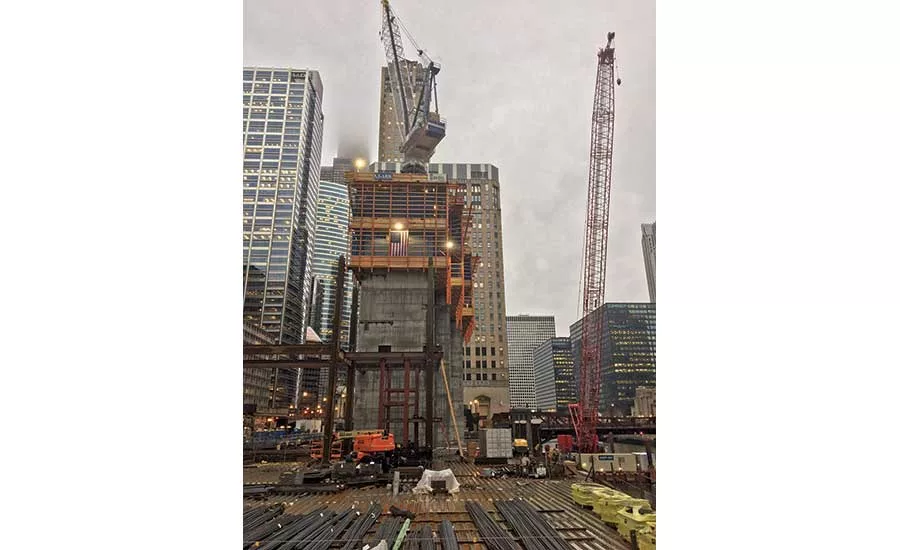
A tower crane in the structure and another on a barge in the river [as it was on Riverside] allowed Clark to perform picks and placements efficiently.
PHOTO BY JEFF YODERS/ENR
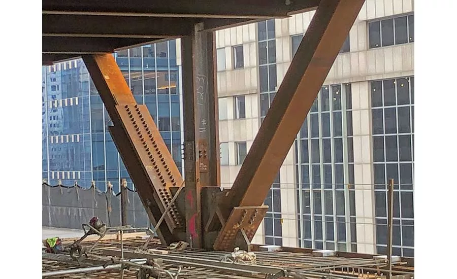
V-shaped structural steel connections aren’t just on the western side of the building. This one’s an east side “trident.” Steel erector Chicago Steel and supplier ArcelorMittal worked closely with Clark to place and secure all such connections as soon as the steel arrived on site.
PHOTO BY JEFF YODERS/ENR
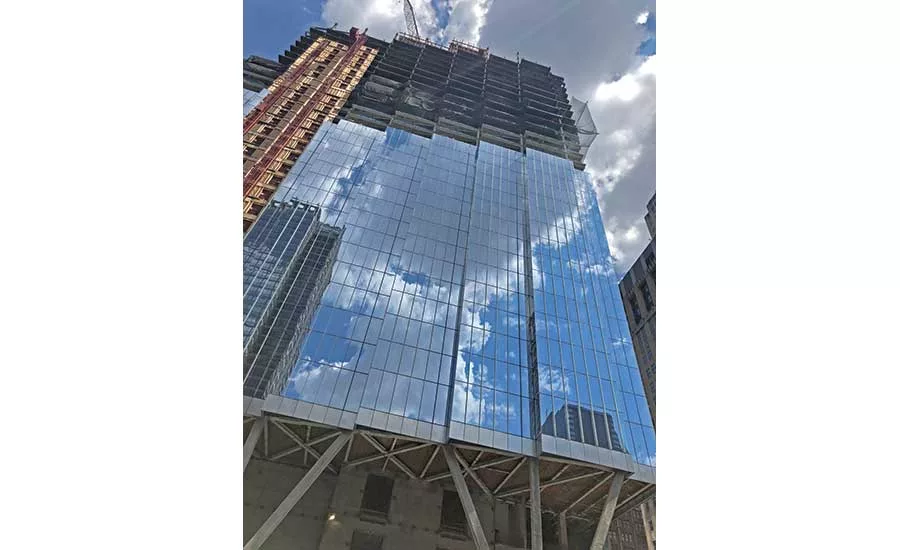
Three supporting tridents and a stepped core allow the west facade of the building to step out with 30-ft-wide, 5-ft setbacks that better match the angle of the river and create more corner offices for tenants.
PHOTO BY JEFF YODERS/ENR
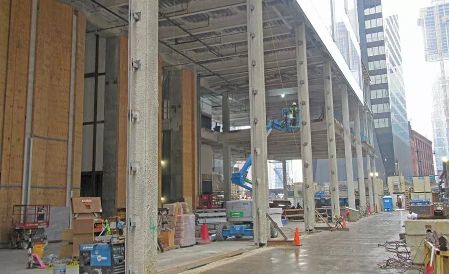
The east side of 110 N. Wacker has more traditional perimeter columns. At ground level the site has a big enough area to be used for laydown of steel and other materials.
PHOTO BY JEFF YODERS/ENR

The trapezoidal site caused Thornton Tomasetti to use a header beam above the tridents and carefully place each column so that the stepped core and the perimeter columns hold the load in different places.
DIAGRAM COURTESY THORNTON TOMASETTI
After taming the tight site of 150 N. Riverside, Riverside Investment and Development, Goettsch Partners, Clark Construction and several other members of that project team found themselves building another office tower directly across the Chicago River from their award-winning project completed just two years ago.
“You don’t often get a chance to bring to bear the lessons learned and all of the efficiencies gained from the start of and the end of a project, and try to roll them immediately to the next one,” says Anthony Scacco, principal at developer Riverside Investment and Development. “Same architect, same contractor, same developer. Those [efficiencies] have borne themselves out. The glass crews are hitting more than 90 panels a day, which is where they finished off on [150 N. Riverside]. So they’re achieving efficiencies as if they’ve been going at it for six months, and they just started three months ago.”
110 N. Wacker is a $760.7-million, 817-ft-tall, 56-story office tower on the site of the former Morton Salt Co. headquarters, a 1958, five-story, low-rise office building that was a classic example of mid-century modern architecture. It turned its back to the river like most pre-2010 Chicago construction and was purchased in 1990 by General Growth Properties, an operator of shopping malls that had used the structure as its headquarters.
“We were fortunate that the city accepted the idea that once you were 55 ft above the riverwalk, it’s the equivalent of open to the sky.”
– James Goettsch, Chairman and co-CEO, Goettsch Partners
Dallas-based Howard Hughes Corp. bought the 43,000-sq-ft site from GGP in 2014 for $12.3 million. Howard Hughes partnered with Riverside to put a 1.77-million-sq-ft office tower on it with a design from Goettsch. Unlike 150 N. Riverside, 110 N. Wacker’s site is not challenged by rail tracks and a tight area for a foundation, but it is a trapezoidal parcel without much space for a city-required 30-ft riverwalk. A compromise between the developers and the U.S. Army Corps of Engineers, which manages the Chicago River for the federal government, over historic preservation of the some elements of the Morton Salt Building also required a stormwater outfall structure near the site—essentially a big hole cut in the steel seawall below it to allow stormwater to flow from the tower into the Chicago River. In May 2017, Bank of America signed on as the anchor tenant of the new office tower committing to rent 500,000 sq ft.
“It was a matter of knowing that we could fit it right, and that we could satisfy some of those critical aspects that we want for a building that’s going to meet the demands of the market,” says Aaron Haas, executive vice president of design and construction management at Howard Hughes. “With the lease requirements that the market expects to see [it was a matter of determing] what kind of density and economies of scale could allow us to overcome some of the site challenges.”
Goettsch’s design opted for three 55-ft-tall steel tridents to hold up the entire western river side of the building and create space for the city-required riverwalk. Chicago has demanded that riverwalks be “open to the sky” and free of obstruction since the 1990s, something that simply would not work on a site as tight at 110 N. Wacker’s, at least not for an office tower of this size. The city was willing to compromise on a solution and has been more responsive to developers in recent years.
“That site was trapezoidal. Which made us go in a direction that I don’t think any of us really thought we were going to go, which is giving it a core that’s kind of stepped, which allowed us to maintain a 45-ft lease span,” says James Goettsch, chairman and co-CEO of Goettsch Partners, who was recently honored with the Council on Tall Buildings and Urban Habitat’s Lifetime Achievement Award. “It was a little atypical, and then the whole riverwalk thing. We were fortunate that the city accepted the idea that once you were 55 ft above the riverwalk, it’s the equivalent of open to the sky.”
The stepped center core plan allows the long conference rooms and open views of the river and west that clients desired. A staggering of the core walls is reflected in a series of rectilinear setbacks along the west facade, maintaining an orthogonal 5-ft planning module. There will be 14 corner offices per floor. The 56 floors themselves have composite steel floor framing and the aforementioned stepped concrete core with a steel outrigger and belt truss system, sawtooth perimeter columns on the west side, two levels of cast-in-place concrete basement and rock-socketed caissons. Even though the whole building is planned to be encased in aluminum and glass curtain wall, the space atop 110 N. Wacker’s tallest setback is defined in the plans as the city’s highest commercial deck.
“I think the fact that [the riverwalk is] not open to the sky makes that side, in effect, like a covered walkway, so that makes it unique,” Goettsch says. “Because the site was trapezoidal, it just happened that it worked out on a 30-ft, 5-ft setback. So every 30 ft, except for that first one, is a 5-ft setback. That gives the building, I think, some of the character we’re always trying to put in an office building.”
Structural engineer Thornton Tomasetti initially had the 45-ft-high tridents going up one more level in the original plan so they could form a triangular base that was more of a traditional truss.
“That way you would have multiple load passing and there’s no inherent instability under unbalanced loading,” says Eric Fenske, vice president at Thornton Tomasetti. “Goettsch and the client didn’t like that, they wanted that office space to be free and clear, which is understandable.”
Fenske said Thornton Tomasetti’s engineers had to look at if there’s live loading on one side of the building and not the other.
“The one column on the very north trident, the very north diagonal of that trident, only goes up about half the building because that’s where the big setback is at,” he explains. “So that had equal loads in it without load balance or anything, meaning that that whole trident, as a whole, wants to rack a little bit. To get around that in our design, we have a really large header beam at the top of these tridents and we diagonalized the floor at level four to take out any horizontal load back to the core. The core is actually there to stabilize it.”
The columns on the edge of the sawtooth are not in an ideal location. Fenske says that ideally, the slab edge of the sawtooth, where it comes back, would be placed on the outside of those columns so you could have a cantilevered beam coming straight off the column rather than a column being tucked inside it.
“Basically, we’ve moved the vertical part of the sawtooth over, the ‘short’ edge of it,” he says. “Normally, we’d want to move them a bit north to have more of a standard framing system, but leasing didn’t want that and that caused us to go through some mathematic gymnastics.”
Of the 66 existing batter piles left over from the Morton Salt Building, general contractor Clark Construction removed 12 batter piles and replaced them around the new foundation with 12 new drilled tie-back anchors. To place most of the steel components of the building, including the tridents and the header, Clark used a barge-based Manitowoc MLC300 on the river and welded and seated them in place so they could work off the steel structure as soon as it left the crane.
“The way we like to engineer, particularly structural construction, is let’s over-crane it, let’s place everything we can,” says Chris Phares, Clark vice president. “Put in as many large components as possible. That helps on quality control. It helps on safety. Because we’re doing less work in the field.”
The stormwater outfall structure for the city sewer next to the site created some problems due to unknown conditions.
“We thought there was a wall so we could just open cut the area to get down to lower level two there by the sewer line and that wasn’t the case,” says Fenske. “We had to put in an earth retention system of sheeting for an extra length of area there to support the dirt and the sidewalk and the road there. The earth retention [system] stayed in place, and we poured our retention walls against it. We didn’t want to put too much load on that sewer. That [geo-]foam actually has a lot lighter density than dirt.”
Fenske says the team is performing a lift every three days now that Clark and its sub-contractors have reached the repetitive floors. Glass has been installed on more than half of the tower. Phares says the project is on schedule for its Q4 2020 completion.
BIM Coordination Enables Smooth Construction
110 N. Wacker used an Autodesk Revit 3D model verification process mandated early in design by developer Howard Hughes Corp. Weekly model updates folding in revisions from various constituent parties were overseen and managed by architect Goettsch Partners from design through construction.
“We have a very, very strong model for coordination of all trades,” says Chris Phares, vice president at contractor Clark Construction. “We’re using a lot of in-place, as-built verifications. We’re using a laser scanner to verify floor point elevations. We laser-scanned and point-clouded the excavation at the end of demolition to make sure that everything was actually going to fit.”
One aspect of the project, the view line from conference rooms, amenity spaces and offices on the river side from which tenants demand good views, was even checked in the model during the conceptual design stage.
“Actually being able to check view corridors early on when we were still in concept and design development allowed us to really optimize the floor plate and [even] adjust column placement,” says Katie Willis, vice president of preconstruction and estimating at Howard Hughes. “So much so that that was something that we were able to coordinate early and make the conscious decisions on where we were putting columns and how we were cantilevering to captive optimum view line.”
Every Thursday, from conceptual design through construction, architect Goettsch Partners would upload an all-discipline model onto the team’s cloud sharing website. Everybody—both developers, the contractor, the engineers, the architect and most subcontractors—had access to the same information every single week.
“It started as internal coordination with our other design consultants, structural, primarily,” says Erik Harris, the Goettsch associate principal who managed the weekly uploads. “Formalizing that process really satisfied everybody that worked on the ownership team, but then we rolled it on to the MEP trades who are working in their own 3D environments, and then we’d coordinate and merge that into a lighter weight NavisWorks model for some of the others. We could see the design evolution when it was at most four days old. Making, on the fly, very quick decisions on tenant changes or prospective changes.”

.webp?height=200&t=1636492974&width=200 "110 NORTH WACKER")

