ENR Midwest’s 2018 Best Projects
Water/Environment: Deep Rock Tunnel Connector Project
The $71.4-million Deep Rock Connector Tunnel Project is part of a new 28-mile network of 189-ft-dia deep tunnels designed to eliminate combined sewage overflows that have plagued Indianapolis neighborhoods during heavy rains.
PHOTO COURTESY OF SOUTHLAND HOLDINGS LLC
The $71.4-million Deep Rock Connector Tunnel Project is part of a new 28-mile network of 189-ft-dia deep tunnels designed to eliminate combined sewage overflows that have plagued Indianapolis neighborhoods during heavy rains.
PHOTO COURTESY OF SOUTHLAND HOLDINGS LLC
The $71.4-million Deep Rock Connector Tunnel Project is part of a new 28-mile network of 189-ft-dia deep tunnels designed to eliminate combined sewage overflows that have plagued Indianapolis neighborhoods during heavy rains.
PHOTO COURTESY OF SOUTHLAND HOLDINGS LLC
The $71.4-million Deep Rock Connector Tunnel Project is part of a new 28-mile network of 189-ft-dia deep tunnels designed to eliminate combined sewage overflows that have plagued Indianapolis neighborhoods during heavy rains.
PHOTO COURTESY OF SOUTHLAND HOLDINGS LLC
Deep Rock Tunnel Connector Project
Indianapolis
Best Project
Owner: Citizens Energy Group
General Contractor: Oscar Renda Contracting/Southland Contracting Joint Venture
Lead Design Firm/Structural, MEP and Tunneling Engineer: AECOM
Civil Engineer: Etica/PCS Engineers
Groundwater Control and Pipe Support Design Engineer: Stiver Engineering
HVAC Support System Design Engineer: Silver Creek Engineering
Pipe Support Design Engineer: JPS Engineers
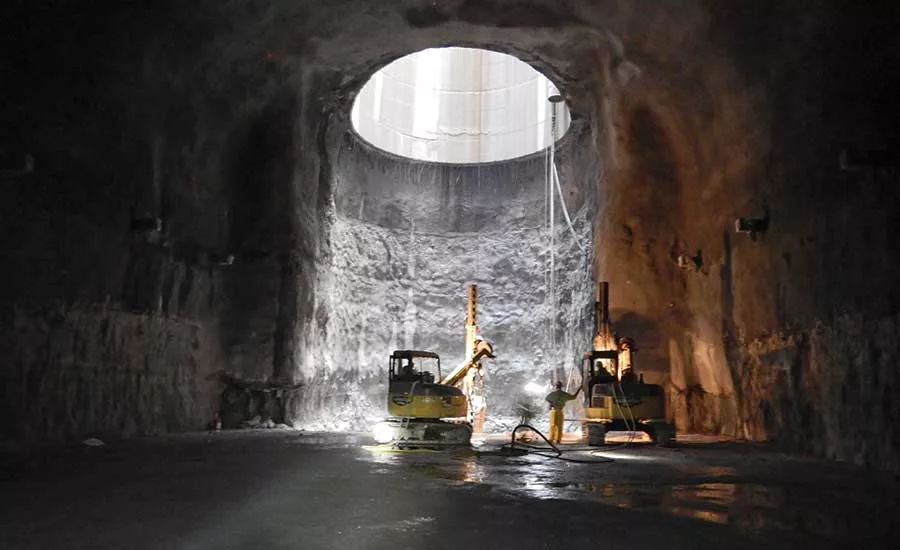
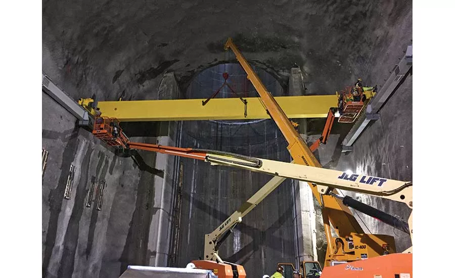
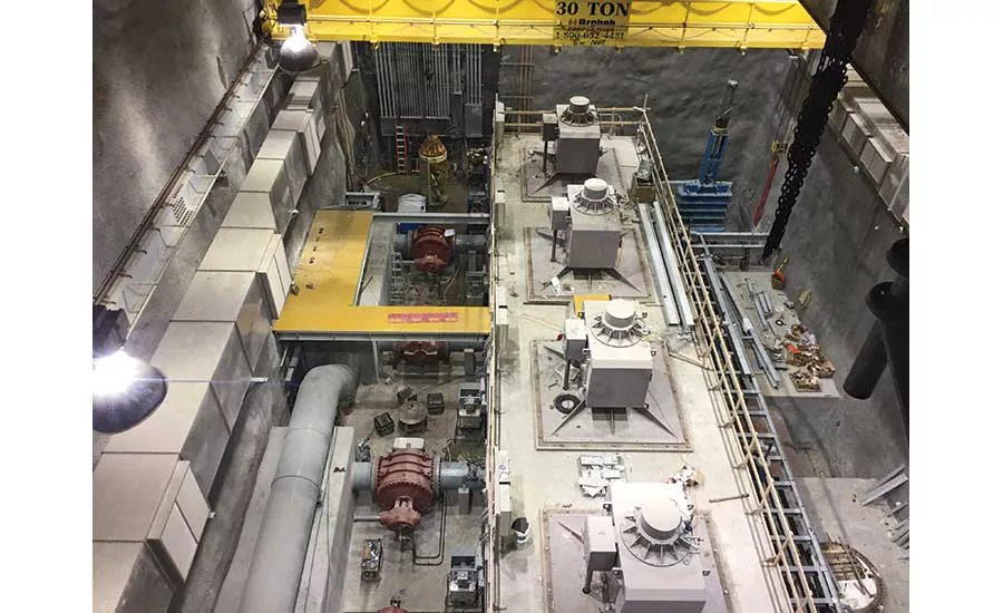
The $71.4-million Deep Rock Connector Tunnel Project is part of a new 28-mile network of 189-ft-dia deep tunnels designed to eliminate combined sewage overflows that have plagued Indianapolis neighborhoods during heavy rains. Once complete, the tunnels will store up to 250 million gallons of stormwater during and after wet weather. The stormwater will then be gradually released for proper treatment at expanded wastewater control facilities. It’s estimated that the system will help prevent more than 5 billion gallons of sewage from entering Indiana’s rivers and streams each year.
Constructed 275 ft below ground, the project’s centerpiece multilevel pump station includes four 1,900-hp motors and four 30-mg/d pumps. Although equipment, including a 30-ton bridge crane, could be lowered to the space via a 44-ft-dia tunnel, Southland Contracting project manager Jose Castillo says the pump station layout left workers with little maneuvering room.
“Everything had to be carefully sequenced so that the components arrived in the right order and with enough space to complete the installation,” Castillo says.
Underground surveys played a critical role for all installations, especially the main tunnel pumps and motors, which required customized formwork that also incorporated anchor locations.
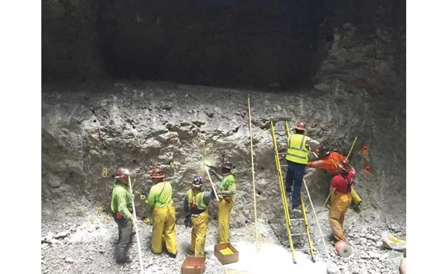
With most of the project’s construction activity taking place below ground, Indianapolis residents were unaware of the complex activity taking place beneath their feet. Excavating space for the pump room cavern and its associated access tunnels and support spaces required the project team to drill and blast through rock with compressive strengths of up to 25,000 psi. More than 130 blasts were carefully planned and timed to control detonation vibrations and protect nearby structures and gas lines. Rock bolts and wire mesh were used as initial support along with a layer of shotcrete, part of an exhaustive rock mass grouting program to combat groundwater flows of up to 500 gpm.
As the pump room would always be susceptible to water intrusion, the project team incorporated a network of slotted pipes as a drainage system beneath the poured base slab. Along with channeling more water to a sump pit compared with the original concept of a pervious concrete drainage layer, the system will be easier to access and maintain through the addition of multiple clean-out points.
