Team Taps Structural Steel for University of Maine Project
Construction team Bridges Atrium to Connect Mechanical Equipment for Ferland Engineering Education and Design Center

A three-story, 108,000 sq-ft multi-use facility for the University of Maine’s Biomedical Engineering Program and the Dept. of Mechanical Engineering will be completed in August.
Courtesy of the University of Maine College of Engineering
Given that the Ferland Engineering Education and Design Center is nearing completion in heavily forested Maine, designers for a three-story, 108,000 sq-ft multi-use facility for the University of Maine’s Biomedical Engineering Program and the Dept. of Mechanical Engineering naturally considered mass timber for the frame. But the team ultimately determined that structural steel and concrete would not only maximize program space, but also offer a better solution for building wet labs for the center’s biology and chemistry departments that are sensitive to vibration. “Structural steel with concrete slabs on deck can be tuned to dampen those vibrations so you don’t have a blurred microscope, for instance,” says Ethan Rhile, vice president of Thornton Tomasetti, the project’s quality assurance quality control structural engineer. Structural steel also helped achieve a flexible building with classrooms, collaborative spaces, labs and constant rearrangement of classroom spaces—a goal for the project, Rhile says.
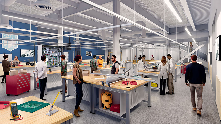
The design team worked closely with the faculty to develop specially configured lab furniture systems that provided a high degree of flexibility.
Rendering courtesy of Ellenzweig
Slated to be completed in August, the $78 million Ferland center launched at the pandemic’s start, adding complexity for the team already facing harsh New England winters and a limited supply of subcontractors in rural Maine. Aside from navigating pandemic volatility by purchasing materials early in 2020, the team has overcome several other challenges, including managing complex floor plans for creating functional yet flexible lab spaces for teaching and research activities. The team also constructed a bridge to connect the new center with an existing building and installed a large skylight and a huge stairway that connects the first three floors and completed considerable work on two chases to connect mechanical equipment for the penthouse.
Despite dealing with these challenges, the team was mindful of detail, allowing engineering components, including structural and mechanical systems to be visible. This encouraged the architect and the engineer to discuss how to design typical connections that were also “clean and architecturally exposed,” says Rhile. The team designed custom gusset plates on the lateral brace frame, for example, to show off an aesthetically pleasing architectural building feature. “One of the primary objectives of the university, the architects and everyone involved was to put engineering on display,” Rhile says. “Rather than build a building and hide what us engineers would call the good stuff behind ceilings and drywall, part of the goal… was to showcase the building structure and the building components.”
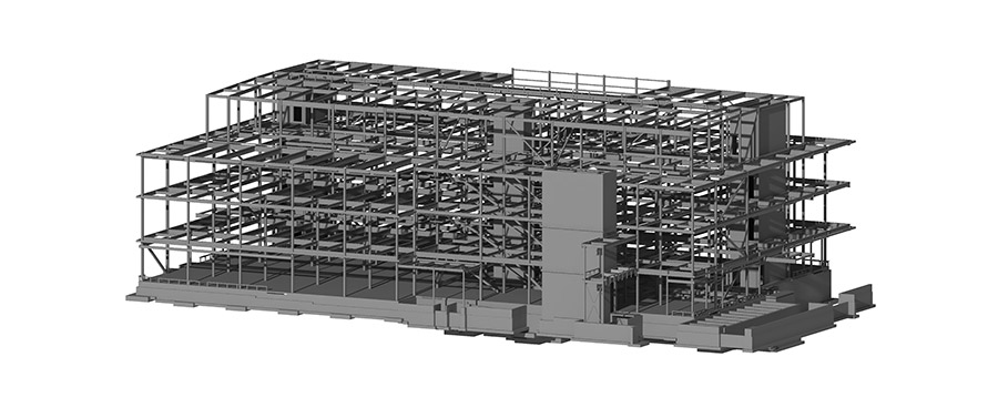
Structural Building Information Model created with Revit. Revit was utilized for multi-discipline design and construction coordination throughout the project.
Rendering courtesy of Thornton Tomasetti
Starting Gate
Following 18 months of design, construction of the Ferland center launched in April 2020, beginning with demolition of the existing building. Since UMaine’s engineering department comprises mechanical, civil, and electrical concentrations, the building must be able to accommodate the unique needs of each discipline, says Matt Tonello, project executive for the project’s contractor, Consigli Construction Co. Inc. “This made the floor plans extremely complex; the team couldn’t repeat the same floor plan for each concentration,” he says.
Designers “worked closely with the faculty to develop specially configured lab furniture systems that provided a high degree of flexibility,” says Michael Lauber, principal-in-charge for Ellenzweig, design architect and lab planner for the project, working with the architect of record, WBRC Architects Engineers.
The team rigged and installed the mechanical bridge through the skylight opening before construction of any interior walls.
Photos Courtesy of Consigli Construction Co. Inc.
“Utilizing overhead service grids to provide power and other services, the lab furniture can be re-positioned and/or combined with adjacent tables to allow students and faculty to adjust the layout to meet the changing needs of pedagogy, student projects, and research activities, while retaining full functionality for power and other infrastructure services.” Lauber says.
In early construction, interconnecting the Ferland center to UMaine’s existing Boardman Hall with a second-floor bridge was challenging on multiple fronts. “We had to survey the elevations of the existing floors,” says Tonello. “To make those connections we’ve had to upgrade some of the windows and openings adjacent to the bridge to make sure they're fire rated.”
Since the team connected a large new different type building structure to one with more square footage, it had to separate them for life safety and fire, he says. “Since Boardman Hall is active, work had to be done either over breaks, holidays or off hours so we didn't impact the classrooms.”
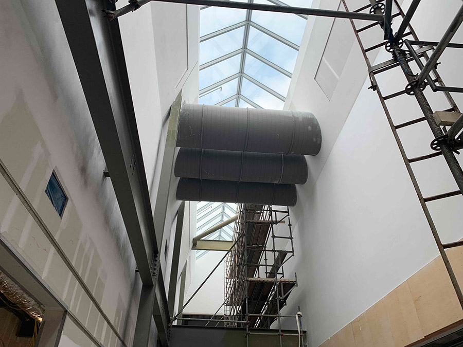
On the third floor, directly above the main corridor the team installed a 12 ft by 170 ft skylight with a rooftop exterior laboratory designed for instrumentation and data collection.
Photos Courtesy of Consigli Construction Co. Inc.
Sky’s the Limit
On the third floor, directly above the main corridor the team installed a 12 ft by 170 ft skylight with a rooftop exterior laboratory designed for instrumentation and data collection, says Kristian Kowal, principal architect at WBRC.
The design team used Revit, Enscape and Sefaria to locate the vertical openings that connect the three occupied floors within the Main Street corridor, Kowal says. “We strategically studied where to locate the openings to allow the greatest potential for daylight to penetrate deep into the core of the building,” he says. “We also considered what density of frit should be applied to the glazing to help mitigate heat gain and temper the quality of the light.”
This main corridor “space was accelerated as it is a focal point of the project and mostly level-five [high-quality] drywall finish,” says Geoffrey Nye, MEP manager at Consigli. The team also wanted to avoid impacting future miscellaneous metals activities.
In connecting three stories in the center of the building by 30-ft by 8-ft structural steel stairs, the structural team conducted some analysis. “Sometimes when a stairway gets really long, there’s concern it’s going to feel bouncy when you’re walking up and down,” says Rhile.
Thornton Tomasetti’s team used inhouse proprietary tools with SAP 2000 structural analysis and design software to analyze vibrations and optimize the overall stairs. Cavanaugh Tocci Associates served as the vibration consultant for the classroom spaces.
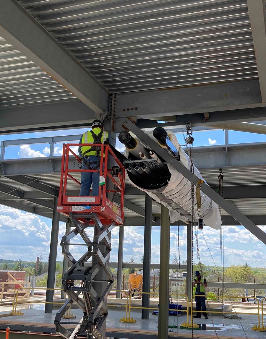
Due to the location of the skylight, the mechanical penthouse is split into east and west sections separated by an atrium, says Jonathan Schiraga, Consigli senior project manager. To connect mechanical equipment for the penthouse the team had to bridge across the atrium, he says “Typically, you would run pipes across the atrium, but the architect [WBRC] didn’t want that visible,” he says. Since large round ducts serving air were already traversing the atrium, the team constructed two 4-ft round mechanical chases (dummy ducts) for enclosing piping inside the ductwork, he says.
Passing through these mechanical bridges are pathways for electrical, controls, security, tele/data, hot and chilled water, domestic water, steam, compressed air, and vacuum piping. “This entire mechanical bridge was coordinated in our BIM to fit within the 4-ft round duct supported by steel channels,” says Nye. “One of the bridges also had to be coordinated to avoid conflict with wind bracing as part of the structural steel.”
The bridges were built on the ground with multiple trades involved in their construction. “Once completed, they were rigged into place shortly after the penthouse level slab on deck was placed,” says Nye. The team prioritized this work because the ducts were rigged through the skylight opening and had to be installed before construction of any interior walls.
It was atypical to undertake the “rough plumbing and gases type work when still in structural steel and slab,” says Schiraga. “But that was our only opportunity to install one large piece and bridge the gap, providing the architect with a continuous duct that would run across the opening.”
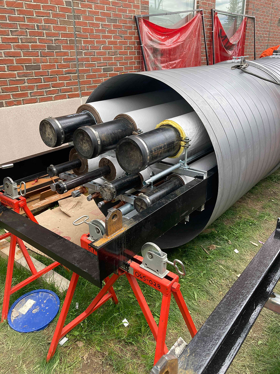
The team prefabricated the mechanical bridges on the ground with multiple trades before rigging them into place.
Photos Courtesy of Consigli Construction Co. Inc.
Maximizing Heat Recovery
Lab construction includes a high level of complex plumbing and mechanical systems. “We’re dealing with gases, vacuums, reverse osmosis water, higher levels of air exchange and heat recovery in addition to fume hoods that require more outside air,” says Tonello.
All labs are 100% exhausted to allow UMaine to reclaim heat in the exhaust air stream rather than letting it escape into the atmosphere, says Consigli’s Nye. The Swiss Konvekta Energy Recovery System is one high performance system that assists with heat recovery from the labs. The glycol water-loop system has four water coils in the make-up air (MUA) unit, two designated for the labs and two in the lab exhaust fan. In winter, the system is guaranteed effective at 81% minimum. “This means 81% of the heating energy required by the supply MUA unit during all heating days/months is provided by energy recovered from the exhaust airstream,” notes Nye. Year-round the system is guaranteed at 54%.
“The bigger coordination issue we faced…was ordering the coils in time for factory installation in the air handling unit and exhaust fan,” says Nye. “However, our strong relationships with vendors allowed us to move at speed and get the submittal pushed through for our order,” he adds.


