


Since late 2017, the 200 structural engineers at Magnusson Klemencic Associates—headquartered in Seattle’s 40-story Rainier Tower—had front row seats for a construction reality show on skyscraper history in the making. Looking out their 32nd-floor office windows, they witnessed the speedy rise of one of MKA’s cutting-edge projects—the 850-ft-tall Rainier Square Tower. RST’s composite steel frame, thanks to its novel Lego-like plate-steel sandwich core, sprang up in only 10 months—twice as fast as a steel frame trailing a concrete core.
In the office, “we had 200 pairs of eyes scrutinizing the work,” says Brian G. Morgen, MKA’s project manager for RST. “Every time there was a big bang, six people would stand up and look out the window.”
MKA engineers were not the only ones interested in RST. Developers, architects, contractors, fabricators, erectors, researchers and other engineers flew to Seattle to see the action. “We led one or two site tours a week for a year,” says Morgen.
One visitor was Michel Bruneau, director of the Structural Engineering and Earthquake Simulation Laboratory at the University at Buffalo and one of three peer reviewers required for RST’s performance-based seismic design. “Having been involved in research on [composite sandwich panels] for over a decade, seeing Rainier Square Tower rise was like watching history being made,” Bruneau says.
Last April, excitement at MKA intensified as the 58-story RST neared eye level, even though it blocked the view north of the iconic Space Needle. “We covered up Ron’s office windows with a thank you note to the erection crew for the hard work,” says Morgen. The sign said “Your crew rocks—from MKA.”

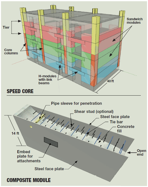
“Ron” is MKA’s chairman and CEO Ron Klemencic—ENR’s 2018 Award of Excellence winner—who also is the mastermind of “speed core,” the American Institute of Steel Construction’s nickname for the high-rise system. AISC is a co-sponsor of performance testing on the modules (see p. 28).
Instead of a concrete core to resist lateral loads, RST has a system of dual cross-tied plate-steel modules. In the field, modules are stacked like Legos, welded and then filled with plain concrete to create a sandwich.
Though the 1.1-million-sq-ft tower, designed by architect NBBJ, is not set to open until early September, for MKA engineers—and the rest of RST’s building team—the riveting part of the show ended Aug. 9, when The Erection Co. topped out the steel structure.
It had taken only 10 months. A traditional concrete core would have been at about level 30, with steel trailing at about level 22, according to MKA.
“The erection went surprisingly spectacularly well,” says MKA’s Klemencic, who all but staked his reputation on RST. His aim with speed core is to usher in an era of swifter, safer and easier high-rise construction (ENR 12/25/17-1/1/18 p. 18).
TEC erected the frame two months faster than Adam Jones, its founder and CEO, had predicted several years ago, when he promised to finish the structure 40% faster than a steel frame with a concrete core.
Jones is an ENR Newsmaker for the speed record (ENR 1/20-27 p. 46). But the veteran erector claims TEC could have finished the frame in 71⁄2 to eight months. With a second tower crane, a better supply of modules and no restrictions on street use, “we could have really rocked and rolled,” Jones says.
Shannon Testa, director of commercial markets for RST’s general contractor, Lease Crutcher Lewis (Lewis), says RST “went very smoothly, and the pieces fit together very well.” There were some challenges but nothing insurmountable, she adds. But she cautions that “there’s a long learning curve with this core. It takes a ramp-up period to understand the nuances.”
Still, Testa says speed core is safer for high-rise construction, compared to concrete. “I think that overall, the industry will move toward this,” says Testa, who reports no deaths or significant injuries on the job.
Cindy Edens, executive vice president of development for Wright Runstad & Co., RST’s developer, calls speed core, “my hero core.” She credits the success of the enterprise to the players, who have been collaborating for decades on novel projects, and to WR’s design-build approach to the core. “We stepped into the unknown and figured it out,” says Edens. “It’s always good to have chutzpah and a can-do attitude,” she adds.
That said, RST “has not been an easy project,” says Edens, who declines—with the RST team—to comment on cost, claims or extras.
RST’s opening was originally scheduled for next month. The tardiness is primarily, but not entirely, due to force majeure delays, including a crane operators’ strike in August 2018 and unanticipated restrictions on street use early last year, from the demolition of the nearby Alaskan Way Viaduct to the opening of its replacement—the State Route 99 tunnel. A rare Seattle snowstorm in February 2019 and more than a dozen high-wind days that prevented hoists from running to upper floors also contributed, says Andy Bench, WR’s project manager.
Edens says the schedule drag had nothing to do with speed core, which allowed work-arounds, such as earlier truck deliveries at 4 a.m.
Early arrival and long waiting times would not have worked for concrete mixers. “I thank my lucky stars we were not a concrete core,” Edens says.
The architecture of the carved-back building, dubbed the “kinky boot,” avoids blocking the iconic Rainier Tower, perched next door on its 12-story golf-tee-like pedestal. To shape the RST boot, columns on the east face slope over as few as two floors and as many as 16. There is no typical floor until floor 40.
For stability, on each side of the core at level 38, three lines of 40-ft-deep steel outrigger trusses, with buckling-restrained braces, span to composite outrigger box columns. BRBs will absorb quake energy. An outrigger belt truss provides redundant load paths.
|
Related Article |
Critical Preconstruction Phase
For speed core, a preconstruction phase is critical. “You need a robust plan” to deal with thousands of module prefabrication hours that reduce time on site, says Kevin Guile, president of steel contractor Supreme Group. The fabricator needs “a solid set of deliverables 10 months to a year prior to normal,” he says.
Lewis figures speed core adds about six months more lead time for prefabrication. Mechanical-electrical-plumbing systems (MEP), slab edges and more have to be coordinated earlier, as well.
The duration of extra lead time for the modules varies, says MKA. It is a function of overall project tonnage, shop hours required, shop capacity for a given fabrication facility and how the fabricator plans on inserting the project into its overall shop capacity.
Core module prefab worked well for RST because of a fairly long demolition phase, followed by a fairly long shoring and excavation phase, says Testa.

Photo By Keith B. Evans
The RST team, aware of the possible pitfalls of a first-of-its-kind job, spent 2.5 years in advance of the mill order, issued in June 2017, hammering out the kinks in the system. In late 2017 and early 2018, the team built two full-scale mock-ups of a single tier—the first for the concrete fill operation and the second for steel erection.
Prefabrication challenges aside, speed core has several jobsite benefits. There is no rebar congestion, typical in seismic zones such as Seattle, for there is no rebar. There is no formwork jumping for there is no formwork. And there is no time wasted by the erector watching the concrete cure. Also, ironworkers and concrete casters stay out of each other’s hair because the concrete fill operation trails steel by four floors.
Work on the core, the gravity structure and decking that doubles as a work platform for welders is concurrent. And there are only steel-to-steel connections, which are simpler than steel to concrete.
For the developer, schedule compression could mean fewer carrying costs for general conditions and an earlier revenue stream.
Apart from the erection race, the RST reality show had its share of suspense for MKA engineers and other Rainier Tower tenants. Early on, geotechnical engineer Hart Crowser determined that due to weak soil, the 85-ft-deep section of the excavation alongside Rainier Tower, if not shored, would undermine the high-rise, turning it from a looming tower into a leaning tower—or worse.
After analysis, HC set movement limits. It also provided minimum size, stiffness and geometric constraints for the structural design, by Ground Support PLC, of a secant-pile shoring wall, with 262 anchors drilled at angles under Rainier Tower and beyond.
Only in the summer of 2018, after Malcolm Drilling Co. installed the shoring, could crews finish the RST dig. Before, during and after, HC monitored Rainier Tower. Movement stayed within set limits.
536 Core Panels
RST’s core, dropping from three to two cells on upper floors, contains 536 modules, including 30 H-shaped panels that integrate link beams over doorways. There are 157 box-column boundary elements, also filled with concrete. Supreme supplied all the outrigger system elements and gravity framing.
“We built the core in the shop,” drastically reducing the duration of site work, says Supreme’s Guile, who calls plant workers the “unsung heroes” of RST.
Modules are 14 ft tall, 21 to 45 in. thick and vary from 30 to 40 ft long. Supreme bought plate from Korea because no domestic mill could roll 14-ft-wide plate that is ½-in. thick. That could change in 2022, when a Nucor mill, under construction, is operational.
There are 350,000 cross rods that penetrate the plates. That meant 700,000 plate holes and 700,000 fillet welds. Panels range from 5 to 20 tons. “We were constantly doing analysis on the mass, the pick point and the capacity of the tower crane,” says Guile.

To meet its start and end dates for module deliveries, Supreme changed its original plan to fabricate all the core modules in its Portland, Ore., plant. Instead, the fabricator split the work, including outrigger element fabrication, among three of its shops and other fabricators. “At the peak of activity, there were seven facilities working on the core,” says Guile.
In the shop, workers first set a plate flat and punched holes 12 in. on center. Then they welded in a truss system to keep modules from racking during manufacturing, shipping and erecting. Next, crews set the other plate and dropped in the rods. They then welded rods on the panel’s exposed surface before flipping the module to weld rods on the other surface.
For the rods’ fillet welds, Supreme and a partner developed a proprietary patent-pending orbital welding robot. An operator would move the portable tool to each weld point.
Panels are open-ended to allow concrete to flow into them from abutting columns. Each column’s two baffle rows are staggered so that the top of one hole in one row is in line with the bottom of the hole above it in the other row. That gave the fill an easy pathway from the columns into the panels, says Darya Saber, Lewis’ project manager.
On Aug. 2, 2018, TEC mobilized to install 42 stanchions to receive the first 5-ft-tall core lift, in advance of construction of RST’s 12-ft-thick mat under and around the core. The stanchions were founded on a nonstructural footing, below the future mat’s elevation. Each stanchion was designed to maintain overall stability of the first core lift, which was “floating” during placement of the mat. The strategy buried the core walls in the mat at the proper and plumb location, says Lewis’ Testa.
TEC then demobilized until after Lewis placed the mat, on Sept. 29, 2018. Then, on Oct. 15, 2018, TEC remobilized. Lewis topped out the concrete last Sept. 29, trailing steel by seven weeks.
During construction, the rule of thumb was that steel couldn’t get more than eight floors ahead of concrete. It was extremely important that TEC finish installing floor decking, so Lewis, which self-performed concrete work, could install rebar and prep it for concrete placement, says Lewis’ Saber.
In a typical sequence, TEC would first erect a two-level tier of speed core and surrounding decking and proceed to the next tier while finalizing decking and welding on the first. Once they completed the second tier, they would move to the third tier in the sequence and then turn over the lowest floor for MEP rough-in and rebar placement. Once that was complete, in roughly four or five days, Lewis would mobilize its placement crew to cast deck concrete. As Lewis placed the lowest floor, TEC progressed to the fourth tier.
Core concrete placement was a bit different because the core concrete had to be done ahead of time to jump the tower crane. Typically, Lewis cast core concrete four floors below the erection deck.
For example, if TEC was erecting levels 21 and 22, crews would make level 17 safe for the placement crew so it could cast the core from level 15 to 16, says Saber. There were times crews were able to place up to two floors of the core at the same time.
The 10,000-psi self-consolidating concrete was pumped through an 11-in.-dia porthole in the outer face of each column. It flowed easily into the abutting panel through the baffles’ 6-in.-dia holes, says Testa.
To keep the tempo, it was important to jump the tower crane before casting the concrete on metal deck. For that, Lewis hired an independent engineer to design supplemental steel for the crane tie-in. It consisted of 16 to 17 beams within the structure that would expand from the north slab edge—where the crane was located—to the core, to transfer loads to the core.
TEC would erect crane tie-in members within the erection sequence. After inspection, Lewis would cast core concrete through the tie-in level. An inspector would then take cylinder samples and break them within one or two days because “we had to achieve 4,000 psi to be allowed to jump the crane,” says Saber.
After the inspector issued its report, Lewis forwarded all the information to the appropriate parties. Then “we would jump the crane,” Saber says.
To give welders access to panels in elevator shafts, TEC built a four-level wood and steel work platform for each shaft. At its top level, each platform hung from shaft framing connections on core walls and internal elevator-lobby wall framing.
Five-Day Tier Cycle
TEC erected a two-level tier in a five-day cycle. Core columns arrived in two-level lengths. For each tier, crews stacked two modules between columns.
The original plan had called for setting all the core elements in the first three days and gravity elements in the remaining two. But the five-month street-use limit, which eliminated a staging lane, meant only two module delivery trucks could arrive each day, for five days, instead of three trucks each day for 31⁄2 days. To receive deliveries, TEC crews would start work at 2:30 a.m.

Photo By Kristine Svehla-Brown/MKA
It cost a “little bit” extra for overtime, says Brett Miller, TEC’s general superintendent.
On day one, beginning in the north-northwest zone, near the tower crane, TEC set core columns for an entire tier. Plumbing and welding came next, including splice welds where columns abut modules, needed to set modules. Crews also set outrigger columns in that zone and the work platforms inside shafts.
On day two, in the same area, workers set the first gravity columns and framing. They then set four or five core modules, followed by interior core modules, to create the core’s two or three core cells.
On day three, TEC set core wall and interior modules in the north-northeast zone. Gravity columns, framing and outrigger columns followed. On day four, crews moved to the southeast and southwest sides, repeating the sequence. On day five, TEC finished gravity framing and jumped work platforms to the next tier.
With the curtain wall up, MKA engineers are no longer paying too much attention to the job outside their windows. The show may be over for them, but it is not for Klemencic, who is busy working on six shorter speed-core office buildings in California.
MKA is so enthusiastic about the core system that—for erectors with welding anxiety—it is involved with research to develop a bolted version. “We are coming up with a bolted splice we hope will provoke equal enthusiasm from others,” Klemencic says.


Post a comment to this article
Report Abusive Comment