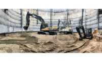
On a project decades in the making, crews will soon begin demolishing a defunct nuclear-reactor caisson in Eureka, Calif., at a site located only a few feet from the Pacific Ocean. However, before workers can begin the arduous task of breaking up the heavily reinforced concrete caisson, the project team must use custom-built drilling machinery from Germany to install unusually deep cutter soil mix (CSM) walls that prevent water intrusion so that the demolition can be done safely.
“In simplistic terms, we are building a ‘soda can’ out of concrete in the ground,” says John Gilbert, project manager with contractor Chicago Bridge & Iron Co. (CB&I) on the $206-million removal and civil works contract. When complete, crews will dewater and excavate the inside of the “can” and remove the concrete caisson structure.
According to the U.S. Nuclear Regulatory Commission, Humboldt Bay Power Plant’s Unit 3 was the first commercial nuclear power plant to feature a below-grade reactor core. Constructed in the late 1950s, the vessel, housed within a 60-ft-dia concrete caisson, was sunk 80 ft underground and nearly 66 ft below sea level.
The plant operated from 1963 to 1976, when it was shut down for annual refueling and seismic modifications. In 1983, plant owner Pacific Gas and Electric Co. (PG&E) deemed the reactor too expensive to restart and began the long decommissioning process.
Mitigating Water
Since most of the caisson sits below sea level, the close proximity to Humboldt Bay presented a major hurdle in decommissioning. A feasibility study conducted by another contractor originally called for a 684-linear-ft slurry wall around the caisson site to minimize groundwater infiltration. In addition, a sloped soil nail wall would provide structural support for the upper excavation, while a sheet pile wall and ring beam shoring system would support the lower excavation.
However, when CB&I took on the project in July 2013, their engineers determined that the method recommended in the study wouldn’t provide enough structural support due to site constraints, since demolition will be done next to a currently operating conventional power plant. CB&I drilled approximately 120 geotechnical bore holes throughout the site, focused in and around the refueling building that sits at ground level directly above the caisson. Through this investigation, the contractor discovered that a clay layer existed at a shallower depth than previously thought, says Alan Brown, CB&I’s geotechnical engineer.
“We were able to factor that into an optimum design for the client,” he says.
CB&I’s method includes construction of a 13-ft-thick CSM wall comprised of five concentric rings of varying depth. The 110-ft-dia “soda can” encompasses the footprint of the caisson and the refueling building, allowing for removal of potential radiological contamination from beneath the building’s spent fuel pool area.
The deepest, outer “E” ring reaches down 172 ft (or 157 ft below sea level) to penetrate the clay layer. The wall works with the clay to minimize groundwater intrusion. “The amount of dewatering without the clay tie-in would be tremendous,” says Brett Mainer, vice president of Drill Tech Drilling & Shoring Inc., the subcontractor installing the CSM wall. “Because it’s a [former] nuclear reactor and every bit of water has to be checked for radiation, it’s not a feasible job without having a water cutoff.”
The other four rings provide structural support for the wall and range in depth from 96 ft to 106 ft below sea level. Engineer-of-record Jacobs Associates performed a 3D finite-element analysis of the dynamic loading, which will primarily consist of groundwater pressure after the interior of the ring is excavated.
Crews are constructing the CSM wall by casting 255 separate panels. Each panel is 3.28 ft thick and 9.18 ft wide. To place the deepest E-ring panels, CB&I procured a custom-built drill rig from German equipment manufacturer Bauer, which took its BG-50 drilling rig and extended the length of the kelly bar—or boom—by around 10 ft. “It’s a one-of-a-kind machine, the biggest of its type in the world,” Gilbert says. A second slightly smaller rig is also being used to place the shorter inner ring panels.
To form a panel, drill operators lower the boom—affixed with cutter wheels at the bottom to penetrate the soil—at a rate of about 2.5 in. to 1 ft per minute. Two injection ports release bentonite, and the cutter wheels mix it with the existing sand and other material during the downstroke. The bentonite performs several functions: It displaces part of the material, suspends the drilled column so the surrounding soil doesn’t cave in and coats the edges of the hole to prevent leeching.
During the downstroke, which takes up to 10 hours, sensors provide nearly 5,000 data points to indicate whether the cutter wheels are on track.
Once the cutter wheels reach the target depth, the operator switches the injection ports to 1,000-psi cement slurry, and the rig tremies out from the hole. The cement mixes with existing soil, which acts as in situ aggregate, to form concrete. Meanwhile, the concrete displaces the bentonite as the kelly bar rises up at about 1 ft per minute.
Given that the custom BG-50 has the longest boom and therefore the deepest reach, “we are setting records every day,” says Harry Herkert, CB&I’s job supervisor. With around 230 of the 255 panels placed, the deepest to date extends 172.44 ft from ground level.
To boost strength and form a cohesive 13-ft-thick finished structure, all of the panels overlap. After a panel is placed and cured for at least a day, an adjacent panel will be drilled, incorporating about 18 in. of the previous panel, which will be ground up by the cutter wheels along with the adjacent soil to form the next panel. Similarly, panels forming each of the five rings overlap by around 9 in. with the adjacent rings.
After placement, concrete samples are collected and subjected to break tests performed throughout the curing process. If a panel is deemed unacceptable for any reason by the engineers, the drill rig can grind up the rejected panel and place a new one. “One of the key reasons that we chose this technology was its flexibility,” Gilbert says. “Unlike a shoring system with ring steel or concrete rings, if you have a repair to make, we just redrill a panel.”
Once CSM wall installation wraps up this summer, the team will begin dewatering the inside. Then crews will finally begin demolishing the caisson’s 3-ft 10-in. thick walls and ¾-in. steel drywell liner.
“It will be like peeling an onion—you just keep taking layers and layers off,” says Reef Anderson, senior project manager with Northwest Demolition & Dismantling, the subcontractor responsible for the caisson removal. Dirt will be excavated around the perimeter of the concrete to expose it, then hydraulic hammers will break up the concrete and hydraulic shears will cut up the rebar and steel embeds. An excavator attached with a tele-dipper (essentially a hydraulic arm with a clamshell attachment at the end) can telescope 90 ft deep into the hole to allow for safer and more controlled demolition than using a crane, Anderson says.
In addition to the CSM wall and caisson removal, CB&I’s contract includes demolition of approximately 65 structures, reclamation of the plant’s seawater intake and discharge canals, remediation of hazardous materials and full site restoration. Work will wrap up in 2018.
“Typically it’s a slow process for the demo and cleanup of a nuclear facility like the one we had out here,” Gilbert says. For example, crews remove radiologically contaminated components using various methods, including concrete scabbling to remove contaminants until getting to a layer that is radiologically clean. “You want a minimum stream of waste going to the nuclear waste disposal site, and you want to maximize the clean stream going off site for disposal, reuse or recycle,” Gilbert says.
To date, 12,623 cu yd of soil have been removed from the site, along with 10,150 cu yd of concrete and other debris, according to Seth Nydegger, radwaste specialist with North Coast Fabricators.
When complete, the majority of the site will be returned to its natural state of rolling hills, grasslands and wetlands.


Post a comment to this article
Report Abusive Comment